Antenna directivity enhancer

a directivity enhancer and antenna technology, applied in the direction of antennas, antenna details, collapsible antennas, etc., can solve the problems of large metal objects between the access point and the computer, create interference patterns, and intermittent wireless connections, so as to improve increase the directivity of the access point antenna, and reduce the effect of signal strength

Inactive Publication Date: 2007-07-17
SZENTE PEDRO A +2
View PDF5 Cites 58 Cited by
  • Summary
  • Abstract
  • Description
  • Claims
  • Application Information

AI Technical Summary

Benefits of technology

[0016]The present invention relates to enhancers for antennas. The enhancers improve the directivity of antennas. Wireless networks offer many advantages, as described above. However, wireless connections can be intermittent. One reason is due to the wireless network antenna. For example, the antenna for an access point, such as a router of a WiFi network, is designed to connect to a computer as long as the computer is in its vicinity, independent of direction. Similar, the wireless card or embedded antenna in a computer is designed to connect to an access point anywhere in its vicinity. The connections should be independent of the relative direction between the computer and the access point. However, there can be large metal objects between the access point and the computer. These objects can create interference patterns. The unfortunate results of the interference are decreased signal strength and intermittent connections. Once a user starts to use a computer, the computer would probably stay stationary for a period of time. It would be beneficial to increase the directivity of the access point antenna and / or the computer antenna, in the specific direction between the computer and the access point. The present invention provides different types of enhancers that can be used to increase the directivity of antennas. Such increase in directivity can often lead to improved connectivity.
[0017]In one embodiment, the enhancer includes a 3-dimensional structure with a predefined 3-dimensional shape when operating to enhance the directivity of an antenna. When not operating to enhance the directivity of the antenna, the 3-dimensional structure can be flexibly collapsed into 2-dimensional flat surfaces, with at least two of the surfaces not required to have any space between them when the structure is collapsed. The collapsed enhancer is more portable than the 3-dimensional structure. Another feature of the enhancer is that the direction where the directivity is enhanced can be adjusted as desired. Such flexibility can be used to accommodate the mobility of, for example, portable computers.

Problems solved by technology

However, wireless connections can be intermittent.
However, there can be large metal objects between the access point and the computer.
These objects can create interference patterns.
The unfortunate results of the interference are decreased signal strength and intermittent connections.
Once a user starts to use a computer, the computer would probably stay stationary for a period of time.

Method used


Image

  • Antenna directivity enhancer
  • Antenna directivity enhancer
  • Antenna directivity enhancer

Examples


embodiment 600

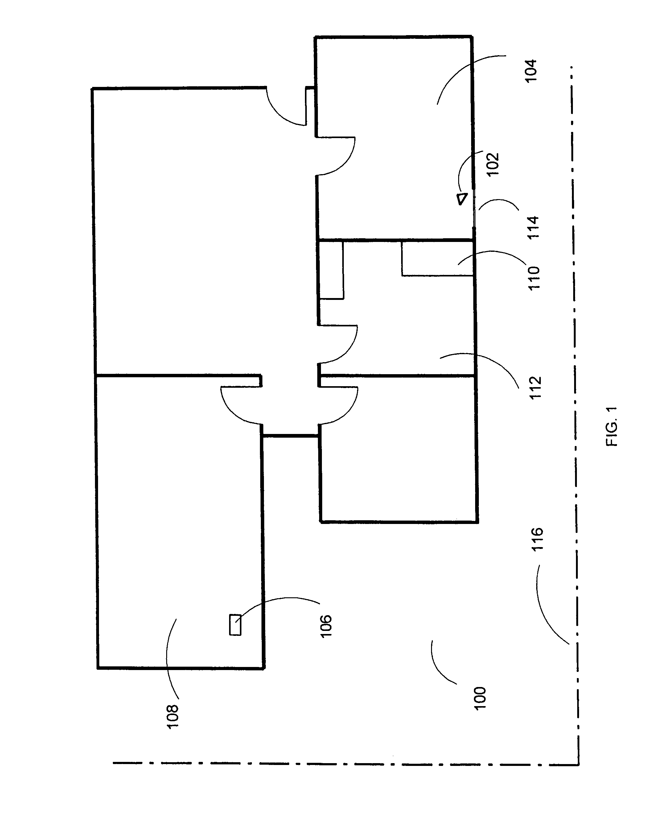
[0099]When all the tubes are inflated, the enhancer will be in its pre-defined 3-dimensional shape. The antenna can then fit through one or two of the holes 634 and 636, with the bottom film 632 supported by, for example, the top surface 203 of the router 204. As in earlier embodiments, there can be an additional tube inserted through the two holes 634 and 636 to set the position of the antenna, if necessary. To collapse the enhancer, one only needs to release air by opening the valve 640. In yet another example, there can also be a non-metallic film on the front side of the enhancer as in the embodiment 600 shown in FIG. 11E.

[0100]The position of the enhancer can be fixed relative to the antenna. In one embodiment, referring back to FIG. 3, the top surface of the router204 is covered by a sheet of hooks, and there is a sheet of loops on the outside of the bottom surface 229. After the optimal position of the enhancer relative to the antenna is identified, that position can be fixed...

embodiment 910

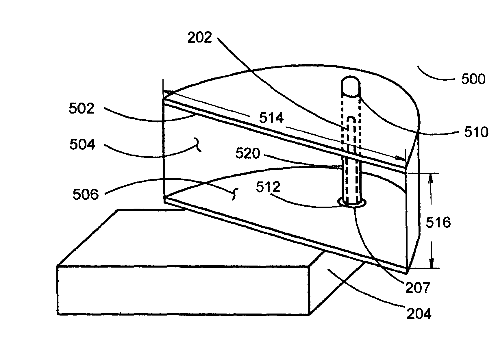
[0124]In yet another embodiment of the invention, the antenna can be in a hole at the vertex of the dihedral surface of the enhancer. The center of the hole can be at the midpoint of the vertex. The tethered antenna can be connected to a port (e.g., the USB port) of the computer. In one embodiment, there can also be a connector, such as a USB connector, at the vertex of the enhancer. The antenna can be placed inside the enhancer and connected to the connector. The connector, whether part of the enhancer or a separate part, can be used to hold the antenna in place within the enhancer. However, sometimes the location and the size of the antenna may not be appropriate to maximize the amount of energy to be coupled into the antenna. FIG. 18B shows an embodiment 910 for such an antenna 912, except that the antenna 912 is positioned on a non-metallic or insulating board inside the enhancer 910. The positioning can be for maximizing the amount of electromagnetic energies to be coupled into...


PUM


Abstract

An antenna directivity enhancer to enhance the directivity of an antenna is disclosed. The enhancer has a 3-dimensional structure in a predefined 3-dimensional shape when operating to enhance the directivity of an antenna. The 3-dimensional structure can be flexibly collapsible into 2-dimensional flat surfaces, with at least two of the surfaces not required to have any space between them when the structure is collapsed. The direction where the directivity is enhanced can be changed as desired. The enhancer can include just one reflecting surface, or at least two reflecting surfaces. In yet another embodiment, the enhancer includes a curved surface when the enhancer is in its predefined 3-dimensional shape.

Description

CROSS-REFERENCE TO RELATED APPLICATION[0001]This application claims priority to U.S. patent application Ser. No. 10 / 687,787, filed Oct. 17, 2003 now U.S. Pat. No. 6,977,624, entitled “Antenna Directivity Enhancer,” and which is hereby incorporated herein by reference.BACKGROUND OF THE INVENTION[0002]1. Field of the Invention[0003]The present invention relates generally to antennas and, more particularly, to a directivity enhancer for an antenna.[0004]2. Description of the Related Art[0005]We live in a networked world. It is not uncommon for a house to have multiple computers, all networked together. In addition to computers, tremendous numbers of electronic devices are deployed all over the world everyday. They can be sensors for collecting information, actuators for providing certain mechanical manipulations, or communication devices, such as cellular phones. Increasingly, electronic devices are also networked together for specific applications. The following descriptions are focus...

Claims


Application Information

Patent Timeline
Patent Type & Authority Patents(United States)
IPC IPC(8): H01Q15/20H01Q15/18
CPCH01Q3/04H01Q15/18H01Q15/20H01Q19/106
Inventor SZENTE, PEDRO A.TONG, PETER P.THOMAS, C. DOUGLASS
Owner SZENTE PEDRO A
Why Eureka
Try Eureka