Half bridge driver

Inactive Publication Date: 2007-07-17
LIEN CHANG ELECTRONICS ENTERPRISE
View PDF1 Cites 16 Cited by
  • Summary
  • Abstract
  • Description
  • Claims
  • Application Information

AI Technical Summary

Benefits of technology

[0016]The half bridge driver of the present invention uses a driver in the conventional half bridge driver to match a push/pull control chip so as to drive the switching actions of the half bridge switch assembly. The present inv

Problems solved by technology

Because of the above limitation, control chips can't be jointly used an

Method used


Image

  • Half bridge driver
  • Half bridge driver
  • Half bridge driver

Examples


Example

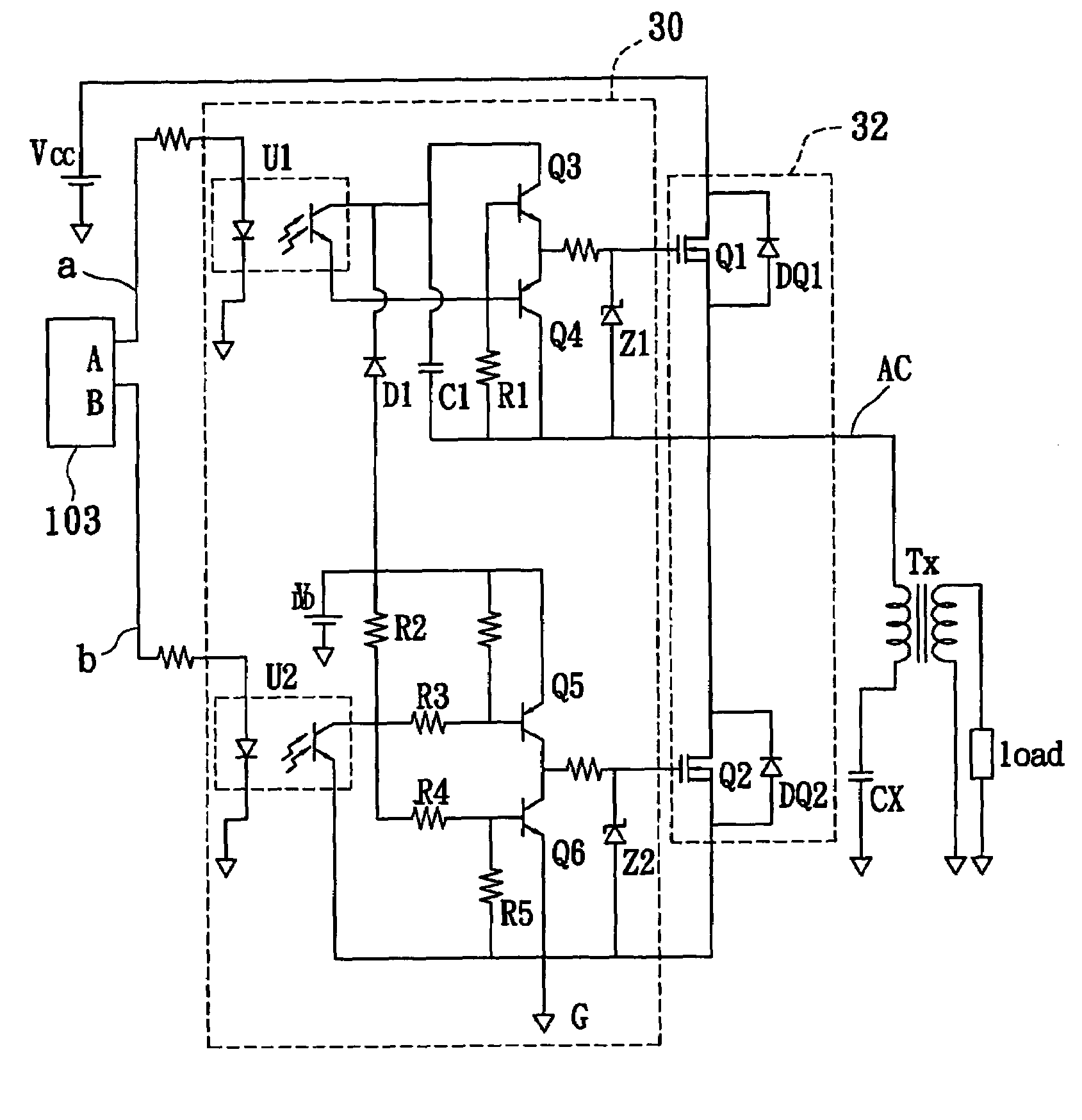
[0024]As shown in FIG. 5, a half bridge driver according to a first embodiment of the present invention is connected to a first side of a transformer Tx to convert a DC power Vcc to an AC power. The AC power provides electric energy required by the load RL via the transformer Tx.

[0025]Reference is made to FIG. 5 again. The half bridge driver according to the first embodiment of the present invention comprises a push / pull control chip 103, a driver 30, and a half bridge switch assembly 32. The push / pull control chip 103 has a first output terminal A and a second output terminal B, wherein the first output terminal A outputs a first control signal a with a duty cycle greater than 50% and the second output terminal B outputs a second control signal b with a duty cycle smaller than 50%. The driver 30 couples to the first output terminal A and the second output terminal B of the push / pull control chip 103 for receiving the first control signal a and the second control signal b. The half ...


PUM


Abstract

A half bridge driver includes a push/pull control chip outputting a first control signal and a second control signal. Each duty cycle of the two control signals is smaller than 50%. A driver couples to the push/pull control chip and a DC power for receiving the first control signal and the second control signal. A half bridge switch assembly with two N-MOSes couples to the DC power, the driver and a transformer, and converts the DC power into an AC power by the driver. The AC power is transmitted to a first side of the transformer.

Description

BACKGROUND OF THE INVENTION[0001]1. Field of the Invention[0002]The present invention relates to a half bridge driver and, more particularly, to a half bridge driver controlled by a push / pull control chip to drive a load.[0003]2. Description of Related Art[0004]The power supply for a backlight source of a TFT LCD panel makes use of a driver circuit to convert energy and turn a cold cathode fluorescent lamp (CCFL) on. Conventional driver circuits can be divided into half bridge-types, full-bridge types and push / pull-types according to different circuit topologies. A driver circuit is a circuit for converting DC power into AC power.[0005]As shown in FIG. 1, a transformer T1 divides the circuit into a front-end circuit on the first side 101 and a rear-end circuit on the second side 102. The front-end circuit on the first side 101 comprises a DC voltage source Vcc, a first switch Q1, and a second switch Q2. The rear-end circuit on the second side 102 comprises at least one capacitor (C1...

Claims


Application Information

Patent Timeline
IPC IPC(8): H02M3/335
CPCH02M7/538H03K17/6871H03K17/785H05B41/2827
Inventor CHAN, CHUN-KONGWANG, JENG-SHONG
Owner LIEN CHANG ELECTRONICS ENTERPRISE
Why Eureka
Try Eureka