Directional microphone

a directional microphone and microphone technology, applied in the direction of frequency/directions obtaining arrangements, transducer types, electrical equipment, etc., can solve the problems of very high demands on the amplitude and phase compensation of the microphone, and the arrangement has a clearly reduced directional effect, so as to achieve good directional effects

Inactive Publication Date: 2007-07-17
SIEMENS AUDIOLOGISCHE TECHN
View PDF3 Cites 79 Cited by
  • Summary
  • Abstract
  • Description
  • Claims
  • Application Information

AI Technical Summary

Benefits of technology

[0007]The invention is based on the object of providing a directional microphone, as well as the use of a directional microphone in a hearing aid device, that lead to a good directional effect given the smallest possible structural shape.
[0010]This is advantageous in that such a directional microphone exhibits a very small and compact assembly. The dimensions of the assembly are predominantly given by the size of the membranes and by the air volumes that, on the one hand, produce the connection to the sound entrance ports and, on the other hand, couple the two membranes with one another. “Acoustic coupling” means a coupling that is generated by a sound wave that forms in the air in the third air volume. A further advantage is that, due to the acoustic coupling of the sound pressures present at both sound entrance ports, membrane vibrations are generated that are dependent on the angle of sound incidence.
[0011]In a particularly advantageous embodiment of the directional microphone, an electrical layer on one of the two membranes and a backplate (counter) electrode to this electrically conductive layer form a capacitive transducer element. Such a capacitive transducer element enables an output signal to be generated from the vibration of the membrane, and has the advantage that the technology of such “capacitive microphones” can be transferred to the directional microphone.
[0012]In an advantageous embodiment, the backplate electrode is arranged between the two membranes (that are arranged parallel to one another) in which a small air gap respectively lies between one of the two membranes and the backplate electrode. To ensure the acoustic coupling of the two membranes, the backplate electrode may comprise air ducts. This has the advantage that the coupling can be adjusted with regard to its strength with the aid of the size of the air ducts.
[0014]In a particularly advantageous embodiment, the directional microphone additionally comprises a signal processing unit and an omnidirectional microphone, by which, with the aid of the signal processing unit, the microphone signal may be used to generate the output signal of the directional microphone corresponding to a directional characteristic. The omnidirectional microphone can either be integrated in a housing with both membranes, or the omnidirectional microphone can by fashioned as an independent unit with separation from the membranes. This embodiment has the advantage that, with the microphone signal of the omnidirectional microphone, a direction-independent comparison measurement is available that, with the aid of the signal processing unit, can be combined with the output signal that is based on the vibration or one or both membranes.

Problems solved by technology

Typically, all directional microphone arrangements possess a clearly reduced directional effect at lower frequencies; moreover, arrangements made up of a plurality of pressure sensors place very high demands on the amplitude and phase compensation of the microphones.

Method used


Image

  • Directional microphone
  • Directional microphone
  • Directional microphone

Examples


Embodiment Construction

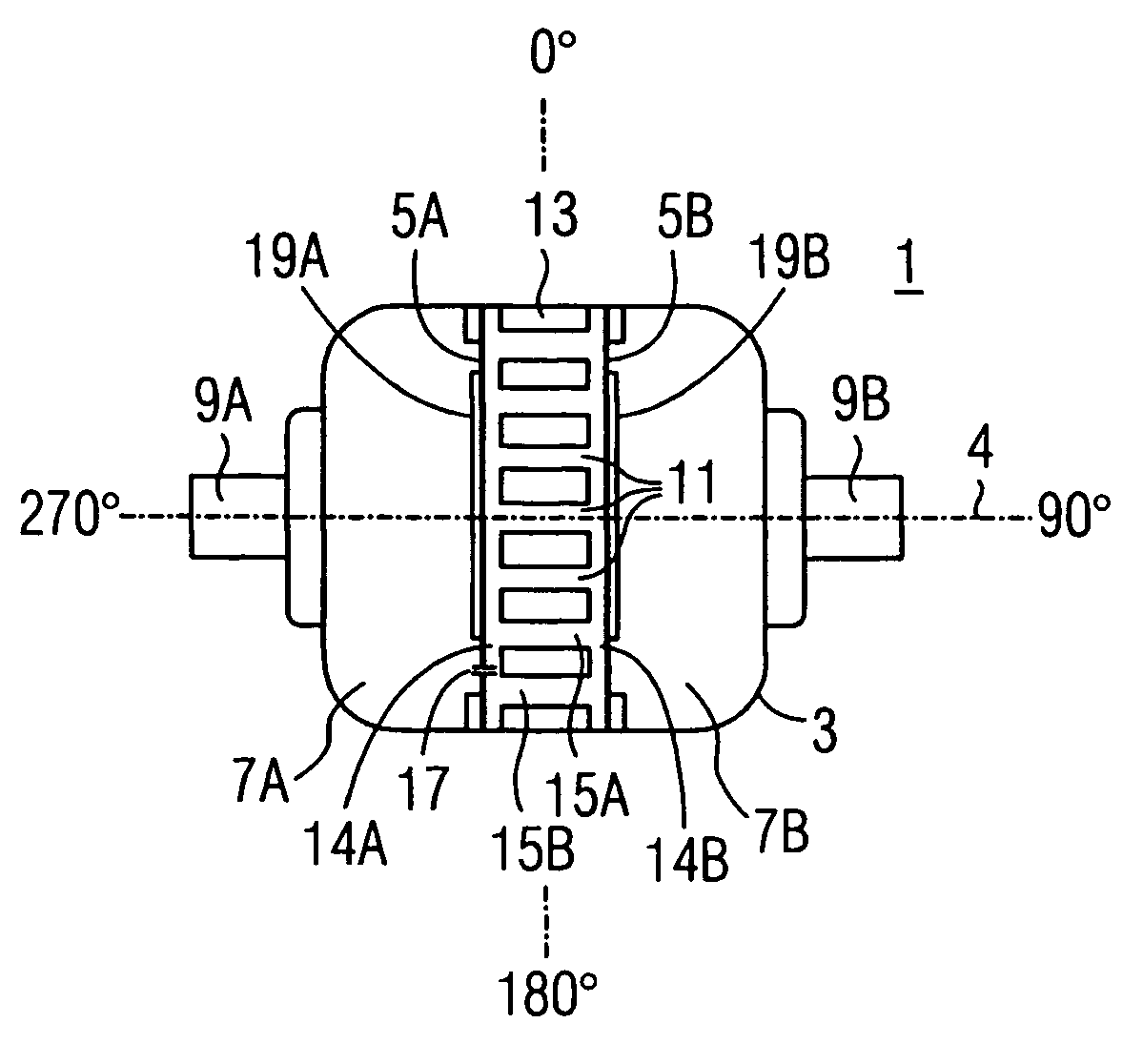
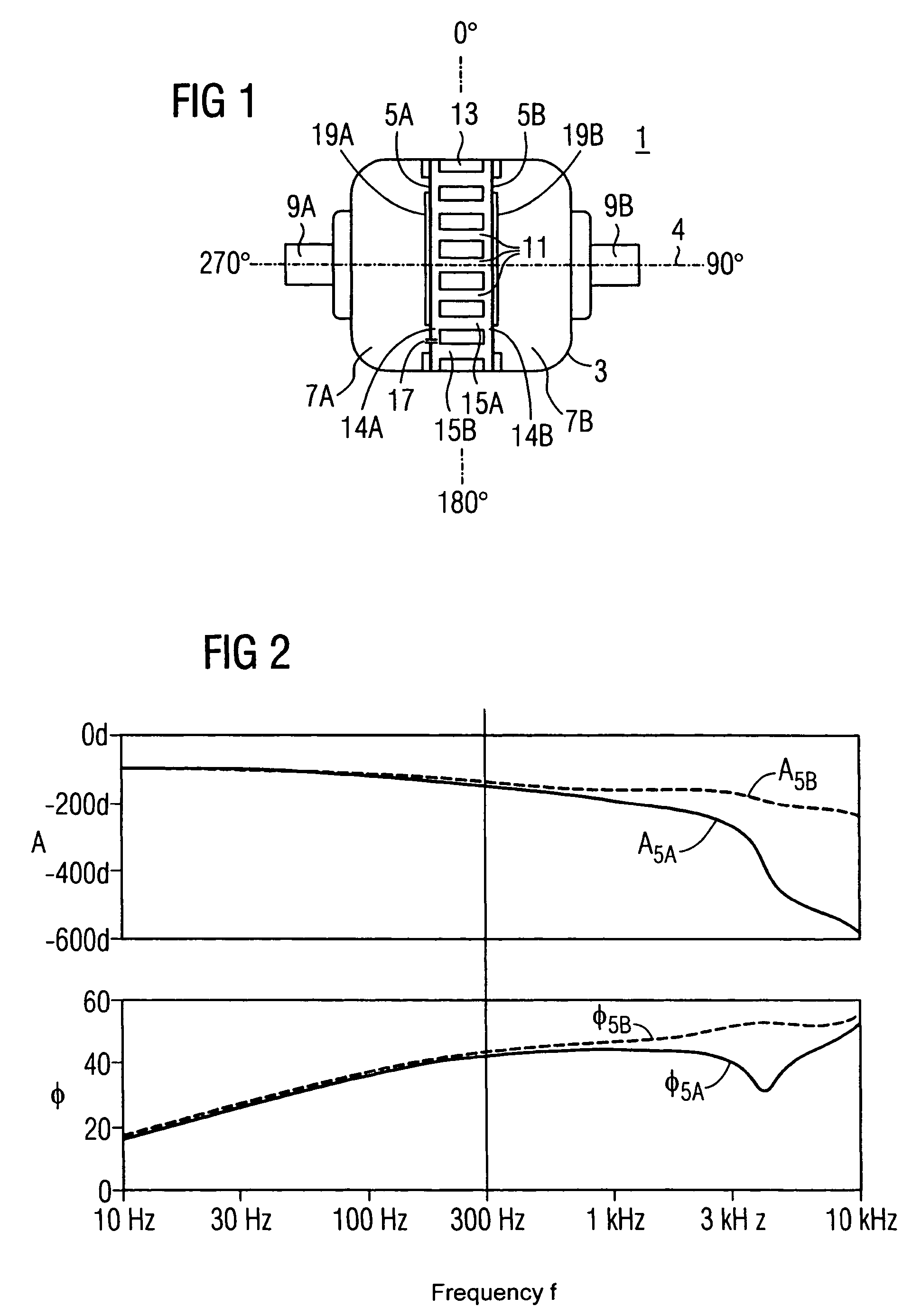
[0023]FIG. 1 shows a schematic assembly of an embodiment of a directional microphone 1 with a cylindrically formed housing 3 in the section along the cylinder axis 4. Located in the housing 3 are two membranes 5A, 5B, preferably arranged perpendicular to the cylinder axis 4, that are preferably attached air-tight to the housing 3 via mountings. The membranes 5A, 5B are in contact with air volumes 7A, 7B. If a sound wave impinges on the sound entrance ports 9A, 9B, it arrives in the air volumes 7A, 7B and effects an oscillation (vibration) of the membranes 5A, 5B, due to the pressure changed by the sound wave.

[0024]A third air volume 11 and a backplate electrode 13 are located between the two membranes 5A, 5B. The air volume 11 is comprised of two air gaps 14A, 14B that exist between the backplate electrode 13 and the two membranes 5A, 5B, as well as of air ducts 15A, 15B which infuse the backplate electrode 13. The air ducts 15A, 15B are, for example, round air channels running para...


PUM


Abstract

A directional microphone system comprises two membranes that, on the one hand, are respectively acoustically connected via an air volume with one of two spatially separate sound entrance ports, and on the other hand are acoustically coupled with one another via a third air volume, as well as an output generator configured to generate at least one output signal of the directional microphone from the vibration of one of the two membranes.

Description

BACKGROUND OF THE INVENTION[0001]The invention concerns a directional microphone.[0002]Modern hearing devices resort to directional microphone arrangements that, via their direction-dependent microphone sensitivity, enable an exclusion of unwanted signals coming from lateral and backwards directions. This spatial effect improves the wanted-signal-to-background-noise ratio, such that, for example, an increased speech comprehension of the wanted signal exists. The conventional directional microphone arrangements are based on an evaluation of the phase (delay) differences that result given a spreading sound wave between at least two spatially separate sound acquisition locations.[0003]In hearing devices, until now, gradient microphones or, respectively, directional microphone arrangements of a first and higher order, comprising a plurality of omnidirectional acoustic pressure sensors, have been used for this. While the first determines the difference (stemming from the mechanical assem...

Claims


Application Information

Patent Timeline
Patent Type & Authority Patents(United States)
IPC IPC(8): H04R9/08H04R1/34H04R1/38H04R1/40H04R25/00
CPCH04R1/38H04R1/406H04R25/402H04R25/405H04R2410/01
Inventor NIEDERDRAENK, TORSTEN
Owner SIEMENS AUDIOLOGISCHE TECHN
Why Eureka
Try Eureka