Locating Device

a technology of locating device and locating device, which is applied in the direction of measuring device, instrument, and detection using electromagnetic waves, can solve the problems of unbalanced feeding of antennas, and achieve the effects of low cost, advantageous directional effect, and high reliability

Inactive Publication Date: 2014-03-27
ROBERT BOSCH GMBH
View PDF6 Cites 12 Cited by
  • Summary
  • Abstract
  • Description
  • Claims
  • Application Information

AI Technical Summary

Benefits of technology

[0004]It is proposed that the antenna be of planar design. A “locating unit” is intended to be understood to mean particularly a unit which is provided for the purpose of ascertaining at least a piece of information about an object that is different than a workpiece. Advantageously, the locating unit ascertains at least a presence of the object in a locating space, particularly in a direction region of one of the antennas. Particularly advantageously, the locating unit ascertains at least a piece of information about a position of the object in the locating space. In particular, “provided” is intended to be understood to mean specifically programmed, designed and / or equipped. In particular, the term “antenna” is intended to be understood to mean a unit which is provided for the purpose of sending and / or receiving a signal. Preferably, the signal is in the form of a magnetic field, in the form of an electrical field, in the form of another signal which appears meaningful to a person skilled in the art and / or preferably in the form of an electromagnetic field. In addition, the locating unit could have an ultrasound sensor and / or an optical sensor, particularly for locating between the sensor and the workpiece. Advantageously, the antenna comprises at least one element. Preferably, two or more antennas have the same element, that is to say that the antennas are at least to some extent of integral design. Advantageously, the locating unit has antennas for different fields and / or signals, as a result of which it is possible to achieve a particularly high level of reliability. Preferably, the locating unit could have an inductive antenna for live lines. In particular, an “element” is intended to be an element of the antenna which radiates a power particularly for the purpose of locating. Preferably, at least the first and second antennas advantageously at least four antennas, are of planar design. Advantageously, the antennas are at least to some extent of integral design, specifically the antennas particularly advantageously have a common ground plane and / or preferably a dielectric of integral design. In particular, an “antenna of planar design” is intended to be understood to mean an antenna which has at least one element which, in particular, at least essentially comprises a flat conductive layer. Advantageously, the layer has a thickness of less than 2 mm, preferably less than 0.5 mm, particularly preferably less than 0.1 mm. Preferably, a ratio between a maximum extent of the element and the thickness of the layer is greater than 5, advantageously greater than 10, particularly advantageously greater than 10. Advantageously, the element has a surface area on one level which is greater than 100 mm2, advantageously greater than 250 mm2. Preferably, the antenna has two conductive layers, at least one of which forms the element. Preferably, the layers extend along different, in particular parallel levels. Advantageously, the layers are arranged at intervals of less than one quarter wavelength, advantageously less than one tenth wavelength, of the transmission signal from one another. Preferably, the planar antenna has a dielectric which is arranged particularly between the layers. Advantageously, the dielectric connects the layers permanently to one another. Preferably, the antenna of planar design is at least to some extent formed by an, in particular, etched printed circuit board. Alternatively or in addition, an insulator, for example a housing portion, could be coated with a conductive face. For this, various methods which appear meaningful to a person skilled in the art are conceivable, such as PVD coating, CVD coating, lacquering, rotation coating, gas-dynamic powder coating and / or cathode sputtering coating. The conductive face is advantageously formed from a metal, that could also be formed from another organic or inorganic substance, such as indium tin oxide. The inventive refinement of the locating apparatus allows the antenna to be of particularly space-saving and inexpensive design. In addition, an advantageous directional effect can be attained with little effort.
[0005]Furthermore, it is proposed that at least the antenna be fed in a balanced form, which means that it is possible to achieve low crosstalk and, in particular, an advantageous direction region in a simple manner in design terms. An “antenna fed in a balanced form” is intended to be understood to mean particularly an antenna which is provided for the purpose of radiating and / or receiving the signal when fed with two signal elements of the same amplitude and opposite phases, particularly relative to a ground plane. Preferably, the antenna has a balun which is provided for the purpose of adjusting the antennas. Preferably, the balun is in the form of a microstrip component. Alternatively, the antennas could be fed in an unbalanced form. Preferably, at least the first and a second antenna are fed in a balanced form.
[0006]In addition, it is proposed that at least the antenna be provided for the purpose of sending and / or receiving on a narrowband basis, as a result of which it is possible to achieve signal generation and signal processing which are particularly simple in terms of design, and, in particular, low legal licensing requirements. In particular, the term “narrowband” is intended to be understood to mean having a bandwidth, particularly a 3-dB bandwidth, of less than 10%, advantageously less than 5%, particularly advantageously less than 1%, of a center frequency. Preferably, at least the first and second antennas are provided for the purpose of sending and / or receiving on a narrowband basis. Advantageously, the locating unit has a signal generator which, during operation, produces a particularly narrowband signal. Preferably, a center frequency for the signal is in an ISM-Band (Industrial, Scientific and Medical Band; ITU-R Regulations 5.138 and 5.150). Particularly preferably, the center frequency is between 2.400 GHz and 2.500 GHz. Alternatively, the antenna could be provided for the purpose of sending and / or receiving on a wideband basis and / or on a plurality of frequencies on a narrowband basis.

Problems solved by technology

Alternatively, the antennas could be fed in an unbalanced form.

Method used


Image

  • Locating Device
  • Locating Device
  • Locating Device

Examples


Embodiment Construction

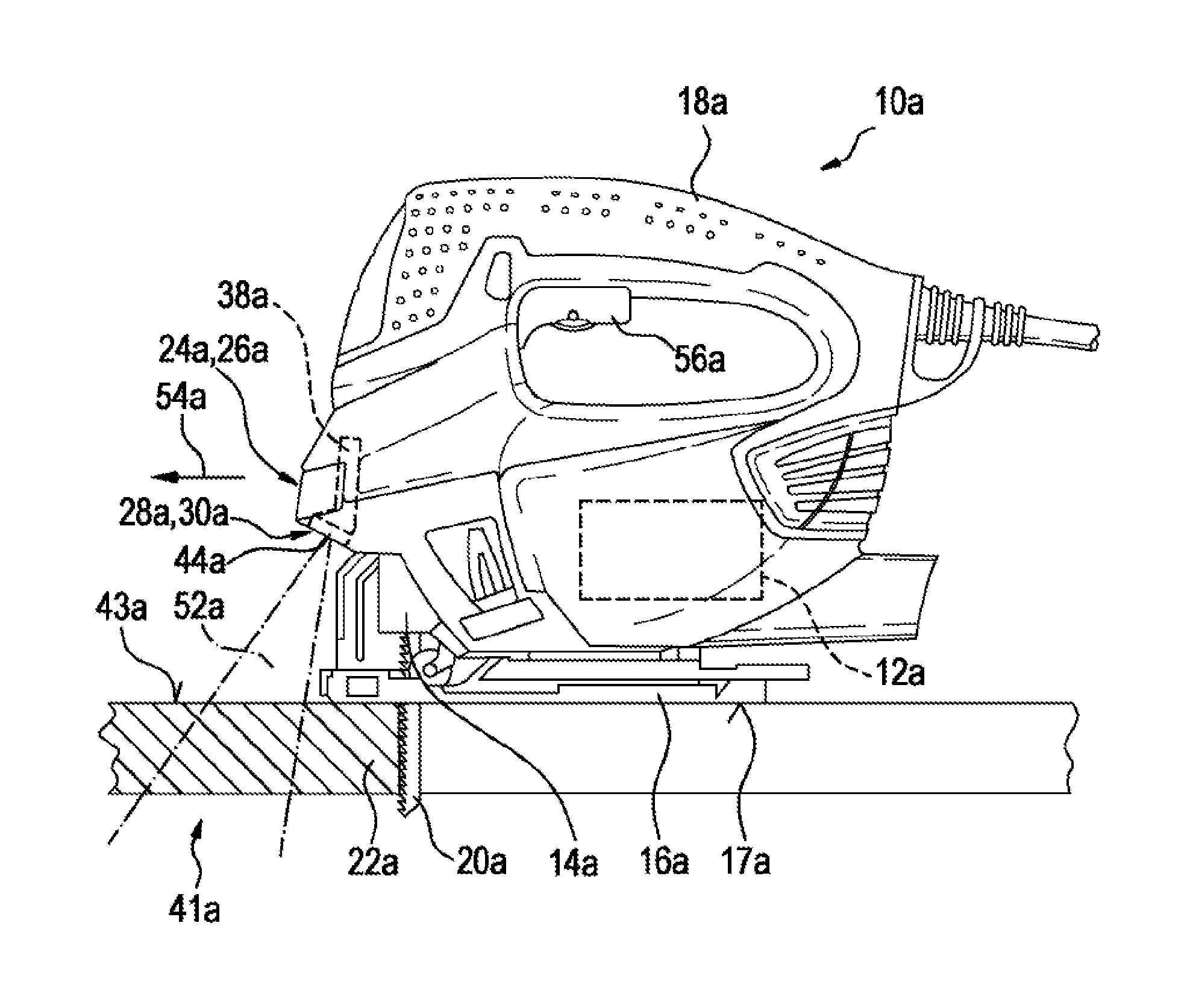
[0032]FIG. 1 shows a hand-held tool 10a, specifically a hand-held machine tool. The hand-held tool 10a is in the form of a jigsaw. The hand-held tool 10a has a drive motor 12a, an insertion tool mount 14a, a workpiece guide means 16a having a workpiece support face 17a and a main grip 18a. During a work process, the drive motor 12a drives the insertion tool mount 14a, specifically in oscillating fashion. In addition, the drive motor 12a drives an insertion tool 20a back and forth during operation. In a ready state, the insertion tool mount 14a mounts the insertion tool 20a. The insertion tool 20a is in the form of a jigsaw blade. During a work process, when moved by a user, the hand-held tool 10a slides over a workpiece 22a on the workpiece support face 17a. The main grip 18a is arranged on a side of the hand-held tool 10a which is remote from the workpiece guide means 16a.

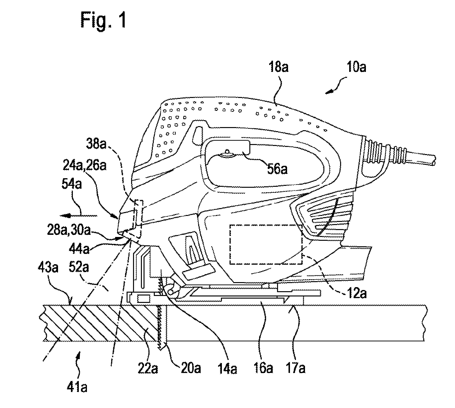
[0033]In addition, the hand-held tool 10a has a locating apparatus 24a, shown schematically in FIG. 2. The loc...


PUM


Abstract

A locating device, in particular a hand locating apparatus, comprises a locating unit which has at least one antenna. The antenna is of planar construction.

Description

PRIOR ART[0001]The invention is based on a locating apparatus according to the preamble of claim 1.[0002]A locating apparatus, particularly a hand-held locating device, having a locating unit which has at least one antenna has already been proposed.DISCLOSURE OF THE INVENTION[0003]The invention is based on a locating apparatus, particularly a hand-held locating device, preferably for detecting objects which are enclosed in a medium, having a locating unit which has at least one antenna.[0004]It is proposed that the antenna be of planar design. A “locating unit” is intended to be understood to mean particularly a unit which is provided for the purpose of ascertaining at least a piece of information about an object that is different than a workpiece. Advantageously, the locating unit ascertains at least a presence of the object in a locating space, particularly in a direction region of one of the antennas. Particularly advantageously, the locating unit ascertains at least a piece of i...

Claims


Application Information

Patent Timeline
Patent Type & Authority Applications(United States)
IPC IPC(8): G01S13/02
CPCG01S13/02B25F5/00G01V3/12G01V3/15
Inventor KRAPF, REINERSGARZ, HEIKOPOHLMANN, MARTIN
Owner ROBERT BOSCH GMBH
Why Eureka
Try Eureka