
Depth map compression technique

a compression technique and depth map technology, applied in the field of depth map compression, can solve the problems of not being able to combine these processes, and not being able to combine the various techniques

Inactive Publication Date: 2007-07-17
DYNAMIC DIGITAL DEPTH RES
View PDF4 Cites 31 Cited by
  • Summary
  • Abstract
  • Description
  • Claims
  • Application Information

AI Technical Summary

Benefits of technology

[0010]It is therefore an object of the present invention to provide a method of compressing depth maps, and in particular it is an object of the present invention to provide a relatively simple technique for representing depth maps in terms of curves, such as bezier curves, and ramp functions that is well suited for real time, or semi real time conversion.SUMMARY OF THE INVENTION

Problems solved by technology

Whilst numerous techniques exist to convert 2D images to stereoscopic images, and in the process create depth maps, to date it has not been possible to combine these processes, such that one technique is utilized to create the depth map, and a different technique used to produce the stereoscopic image.
That is, merging of the various techniques has not been possible, as existing systems are not able to process a depth map produced by a different process.
The inability to combine processes can lead to the same 2D image being processed by a number of different techniques, thereby producing respective depth maps.
The task of analyzing a 2D image for conversion to a depth map can be complicated and in some cases time consuming, and it would be preferable to avoid the need to repeat this task depending on the overall 2D to 3D conversion process selected.

Method used


Image

  • Depth map compression technique
  • Depth map compression technique
  • Depth map compression technique

Examples


Embodiment Construction

[0024]The Applicants have in prior applications AU 10884 / 97, PCT / AU98 / 01005, and Australian Provisional PR1197, the contents all of which are herein incorporated by reference, disclosed various techniques used in the conversion of 2D images to stereoscopic images. These techniques in part disclosed the creation of depth maps and the encoding of these depth maps. However, these techniques only considered the use of depth maps created as part of the respective process. They did not deal with a depth map created by a different process.

[0025]Accordingly, if we assume that a depth map has been created either singularly, or as part of a conversion process, and that that depth map has been transmitted, retained or recorded in some way, then the present invention can be adopted to convert the depth map for transmission and / or further processing so as to display stereoscopic images.

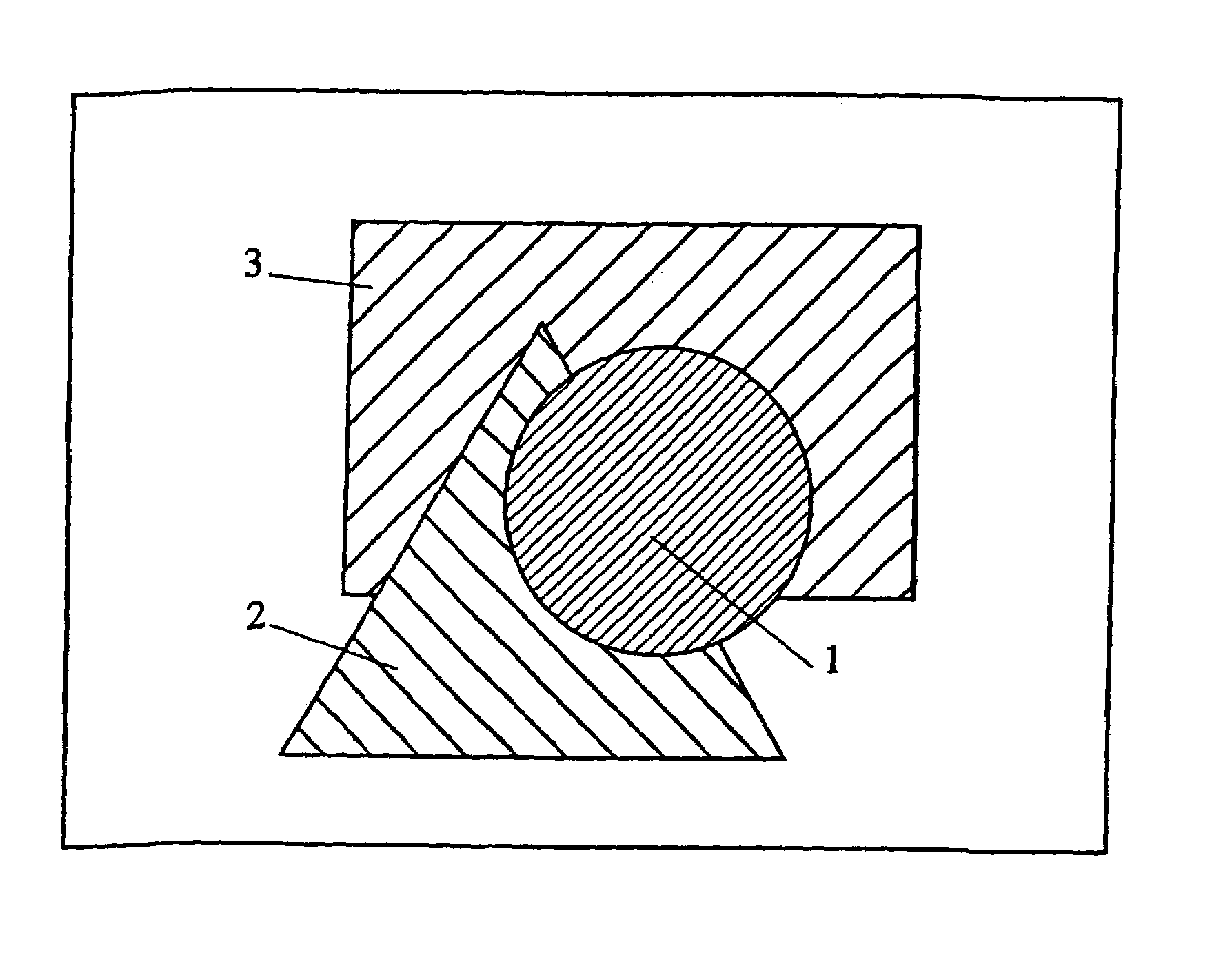
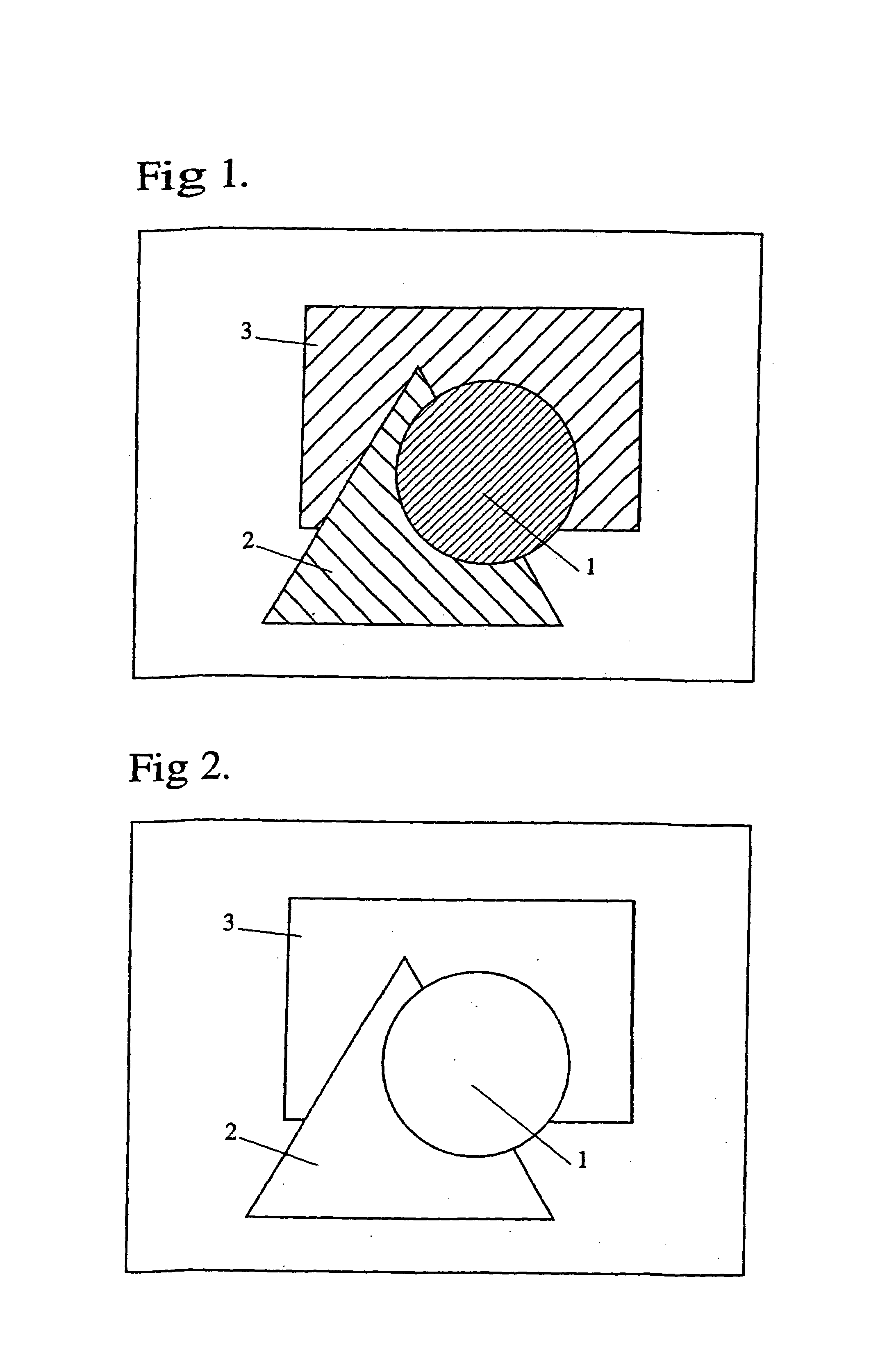
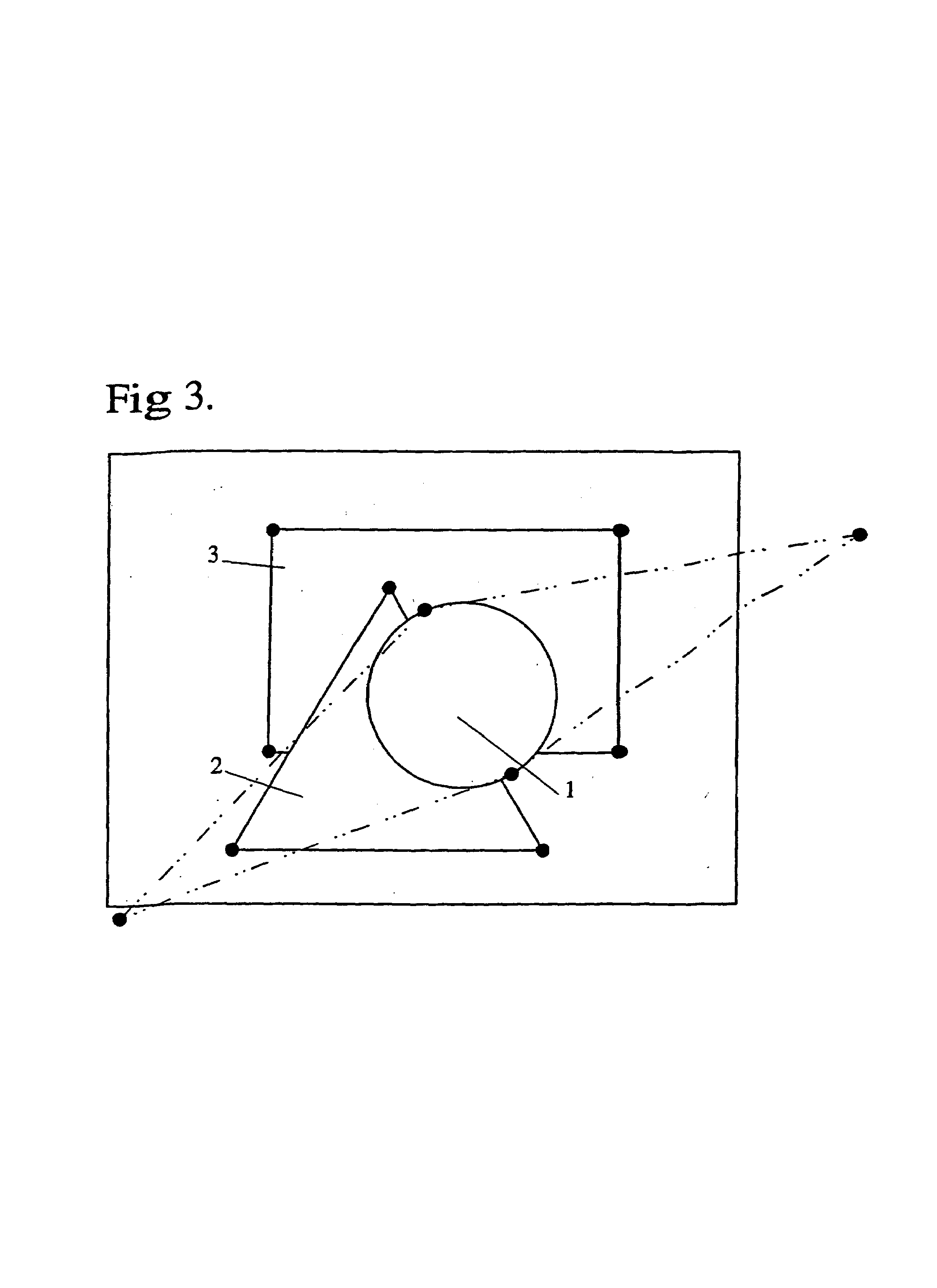
[0026]Referring now to FIG. 1, there is shown by way of example a single video frame of a depth map representat...


PUM


Abstract

A method of compressing depth maps including the steps of determining the boundary of at least one object within a depth map, applying a curve to the boundary of each object, and converting the continuous depth data within an area bounded by the curve into at least one ramp function.

Description

CROSS REFERENCE TO RELATED APPLICATIONS[0001]This is a U.S. National Phase Application under 35 U.S.C. § 371 of International Application No. PCT / AU00 / 01402 filed Nov. 17, 2000, which was published Under PCT Article 21(2) in English, which claims priority to Australian Application No. PQ4166, filed Nov. 19, 1999, the entire contents of which are incorporated herein by reference.FIELD OF THE INVENTION[0002]The present invention is directed towards a method of compressing depth maps, and in particular a method of representing depth maps in terms of curves, such as bezier curves, and ramp functions that is well suited for real time, or semi real time processing.BACKGROUND ART[0003]In converting 2D images into left and right eye images for stereoscopic viewing it is known to create depth maps to assist in the transmission and creation of the 3D image. Generally speaking, the creation of a depth map refers to a technique whereby each object in a scene is allocated a unique attribute (typ...

Claims


Application Information

Patent Timeline
IPC IPC(8): G06K9/36G06T19/00G06T9/00
CPCG06T9/001G06T9/00
Inventor HARMAN, PHILIP VICTORMILLIN, ANDREW
Owner DYNAMIC DIGITAL DEPTH RES
Learn More