Reciprocating counterweight structure for a reciprocating saw

a reciprocating saw and counterweight technology, applied in the field of hand-held reciprocating saws, can solve the problems of unwieldy, difficult manual movement of the saw blade, and difficulty in manually moving the saw blade back and forth,

Inactive Publication Date: 2007-07-24
BLACK & DECKER INC
View PDF39 Cites 24 Cited by
  • Summary
  • Abstract
  • Description
  • Claims
  • Application Information

AI Technical Summary

Problems solved by technology

Manually sawing these materials would be a difficult and time consuming undertaking.
Further, many applications require a saw to be used in a confined area where it would be even more difficult to move a saw blade manually back and forth.
This configuration causes the saw to be longer than necessary, which can render impossible, or at best complicate, some cuts to be performed in a limited space.
A long saw is also generally awkward to use and unwieldy, and is difficult to store when not in use.
Furthermore, in some known reciprocating saws, the housing for the saw assembly is unnecessarily complicated and expensive.
First, the exterior surface of the gear box can be expensive to manufacture. For aesthetic and comfort reasons, the external surfaces of the saw are generally smooth and polished. Since, with this design, the exterior surface of the gear box is also an external surface of the saw, at least a portion of the exterior surface is sometimes manufactured to be smooth. Manufactu

Method used


Image

  • Reciprocating counterweight structure for a reciprocating saw
  • Reciprocating counterweight structure for a reciprocating saw
  • Reciprocating counterweight structure for a reciprocating saw

Examples


Embodiment Construction

[0022]The preferred embodiments of the invention pertain to a hand-held reciprocating saw. Although the invention is described in connection with a particularly preferred arrangement of components, various alternative configurations are also possible. Modifications to the preferred embodiments will be readily apparent to those skilled in the art without departing from the spirit and scope of the invention. Thus, the following description of the preferred embodiments are illustrative only. For convenience, similar elements are designated throughout the drawing figures with the same reference numerals.

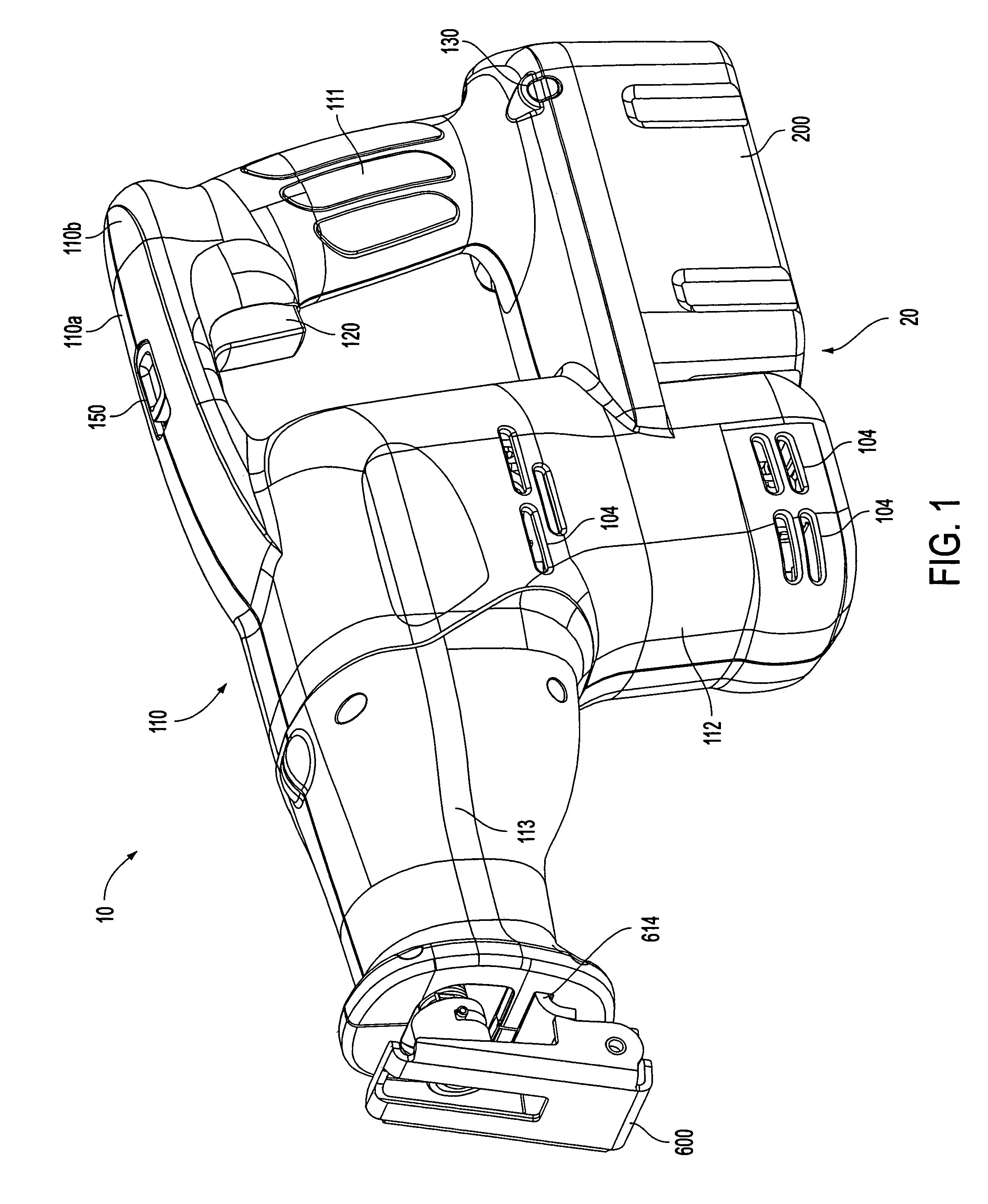
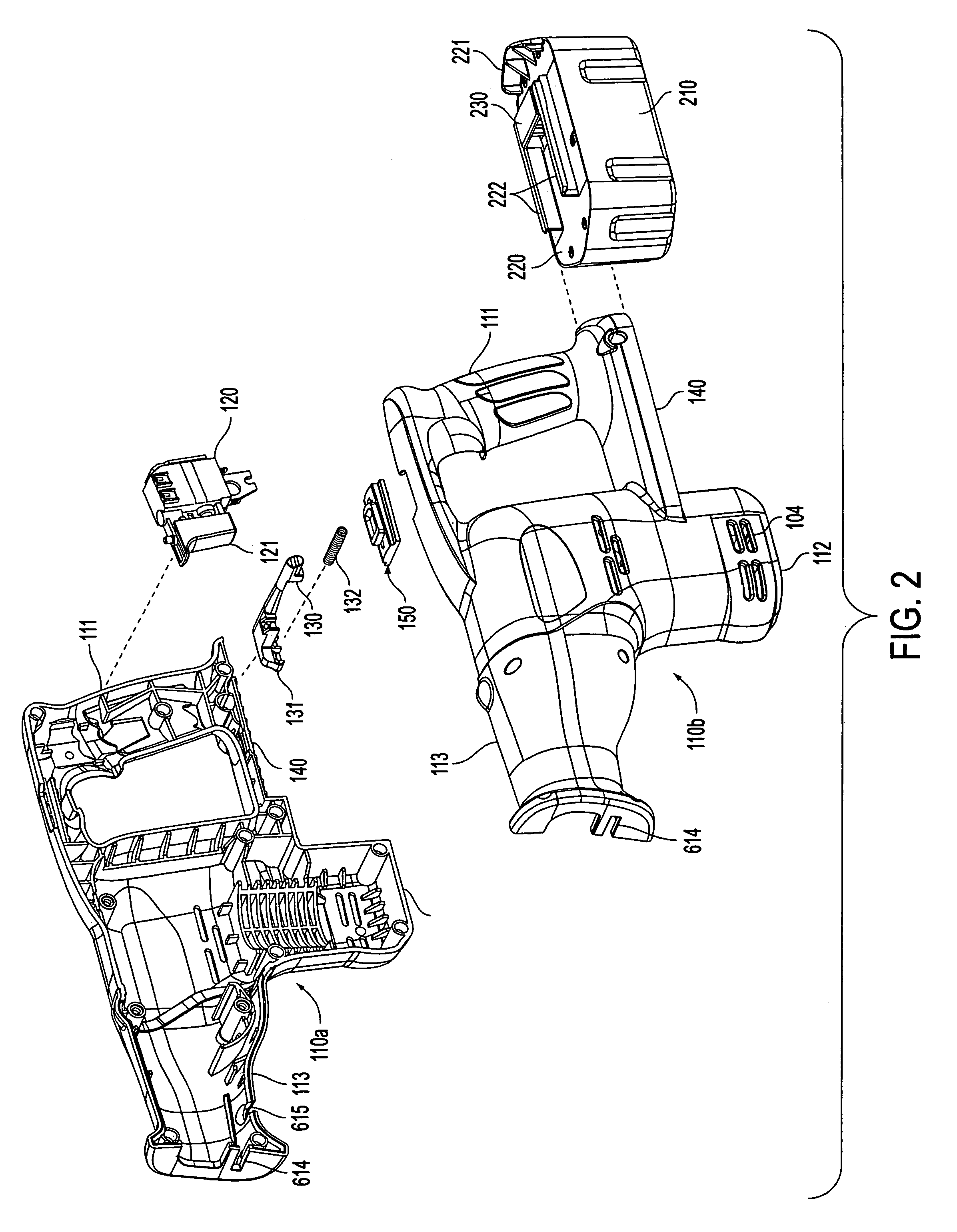
[0023]With reference to FIGS. 1 and 2, the reciprocating saw 10 includes a two-piece housing 110 comprising two mating clam-shell halves 110a and 110b. The two-piece housing 110 may be injection molded plastic in which each half preferably includes a plurality of matching bosses and bores for receiving fasteners (not shown) which hold together the two mating clam-shell halves 110a and 11...


PUM

PropertyMeasurementUnit
Thicknessaaaaaaaaaa
Radiusaaaaaaaaaa

Abstract

A counterweight in a reciprocating saw counterbalances a reciprocating shaft assembly adapted to hold a saw blade. The counterweight is supported for reciprocating motion by slides which ride within slots formed in a housing adapted to hold the reciprocating mechanism.

Description

[0001]This application is a continuation of U.S. patent application Ser. No. 10 / 364,472, filed Feb. 12, 2003 (issued as U.S. Pat. No. 6,810,589), which is a divisional of U.S. patent application Ser. No. 09 / 627,780, filed Jul. 28, 2000 (issued as U.S. Pat. No. 6,568,089) which is a continuation-in-part of U.S. patent application Ser. No. 29 / 123,137, filed May 10, 2000 (abandoned), which is a continuation-in-part of U.S. patent application Ser. No. 29 / 105,953, filed Jun. 4, 1999 (abandoned).BACKGROUND OF THE INVENTION[0002]This invention relates to the field of power tools and in particular to the field of hand-held reciprocating saws.[0003]Reciprocating saws are often used by tradesmen, such as carpenters, plumbers, and electricians for making rough cuts in wood or other hard materials. Manually sawing these materials would be a difficult and time consuming undertaking. Further, many applications require a saw to be used in a confined area where it would be even more difficult to mo...

Claims


Application Information

Patent Timeline
IPC IPC(8): B23D49/10B23D49/16B23D51/16
CPCB23D49/162B23D51/02B23D51/16F16F15/28Y10T74/2183Y10T74/18208Y10T24/1903Y10T74/18248Y10S30/01
Inventor LAGALY, MICHAEL ANTHONYMOOTY, THOMAS ARNOLDNICHOLS, JR., JAMES PIERCECLOWERS, EARL ROGERPOPIK, MATTHEW GEORGE
Owner BLACK & DECKER INC
Why Eureka
Try Eureka