
Cushion pad structure for a carpet installation tool

a technology for installing tools and cushion pads, which is applied in the direction of floor fabrics, constructions, wire tools, etc., can solve the problems of re-installing the entire carpet, presenting pattern matching problems, and uncoordinated patterns on walls or furnitur

Inactive Publication Date: 2007-07-24
ALLIED ARROWS ASSOCS
View PDF5 Cites 0 Cited by
  • Summary
  • Abstract
  • Description
  • Claims
  • Application Information

AI Technical Summary

Benefits of technology

The cushion pad structure effectively protects knee and ankle joints while efficiently transferring impulse force, minimizing injury risk and enhancing installation tool performance.

Problems solved by technology

Additionally, many carpets and rugs present pattern matching problems, which may arise from the pattern in the carpet or rug itself, or with another pattern in the environment, such as patterns on walls or furniture appear uncoordinated.
However, while it is sometimes impossible to re-install the entire carpet, it may be possible to make sectional adjustments.
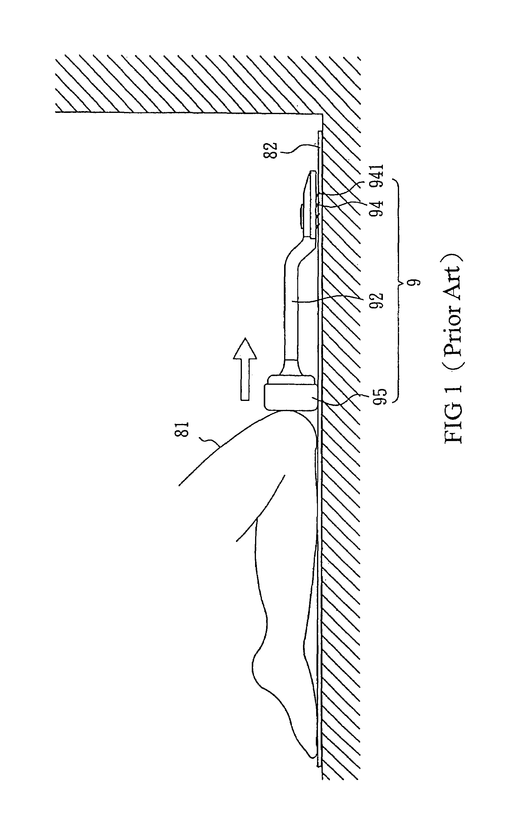
Additional, the carpet installation tool may be used very frequently by the technician, which might cause temporary or sustained or even permanent chronic injury to the knee or ankle joints of the technician.
Therefore, there are many technicians in this field that have stopped working because of injuries to knee or ankle joints.
Softer cushion pads provide better protection for knee and ankle joints, but do not efficiently transfer the impulse force; on the other hand, harder cushion pads directly and efficiently transfer the impulse force, but they also create larger reaction forces to knee and ankle joints, which cause unnecessary injury.

Method used


Image

  • Cushion pad structure for a carpet installation tool
  • Cushion pad structure for a carpet installation tool
  • Cushion pad structure for a carpet installation tool

Examples


Embodiment Construction

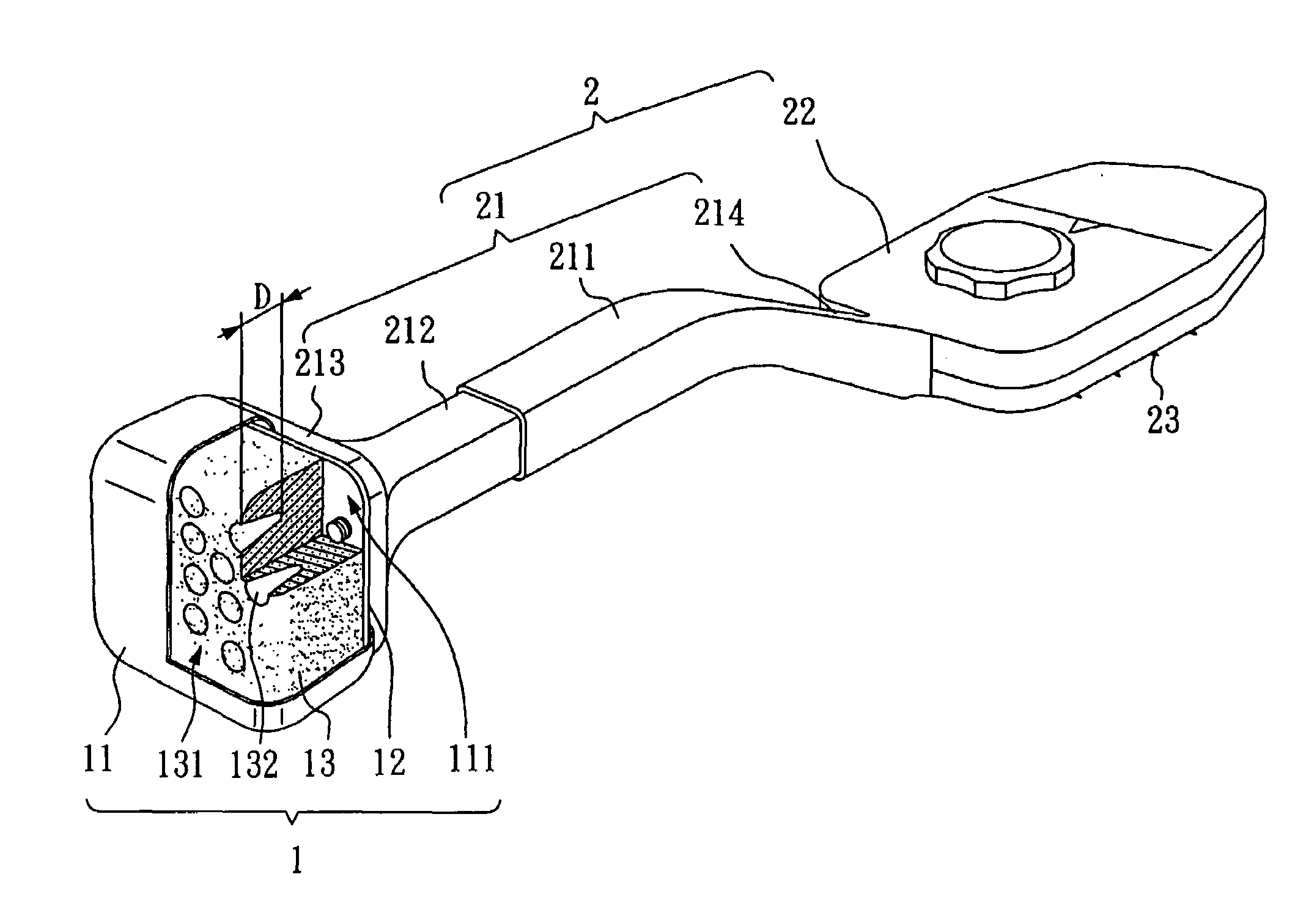
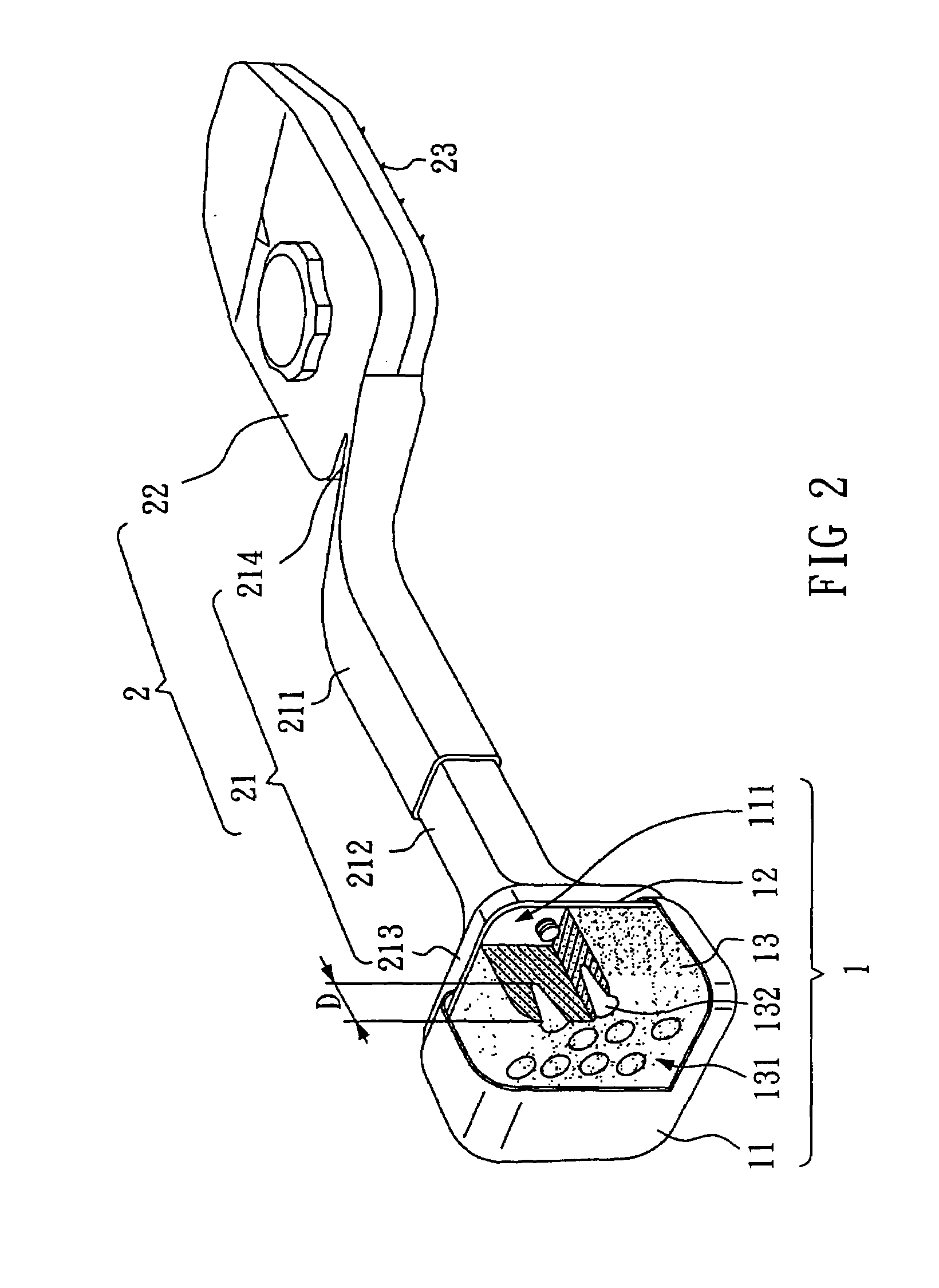
[0029]Please refer to FIG. 2 and FIG. 3. FIG. 2 provides a perspective view of a first embodiment of the present invention. FIG. 3 is a local exploded view of the first embodiment of the present invention. As shown in FIG. 2, a cushion pad 1 of the present invention is mounted at the rear end of a carpet installation tool 2.

[0030]The carpet installation tool 2 comprises a connecting arm 21 and a claw disk 22. As shown in FIG. 2, the connecting arm 21 comprises a front arm 211 and a rear arm 212. One end 214 of the front arm 211 is connected to the claw disk 22, and the claw disk 22 has a plurality of claws 23 extending down and forward (only four claws 23 are shown in the drawing due to the viewing angle). The rear arm 212 is disposed in the front arm 211 so that the length of the connecting arm 21 can be adjusted by the technician. One end 213 of the rear arm 212 is a locking end, which has a cushion pad 1.

[0031]As shown in FIG. 2, the cushion pad 1 comprises a covering layer 11, a...


PUM


Abstract

The cushion pad structure of the carpet installation tool comprises a rubber covering layer, a rubber foam body and an assembly board. The foam body is disposed in the covering layer. The foam body comprises a thrust face, which has a plurality of the first holes with at least a predetermined depth. The thrust face is designed so that a technician's knee or heel receives less reaction force from the impulse imparted due to the plurality of the first holes and softened hardness. Under the impulse force, the hardness of the advance gradually cushioning structure increases its hardness slowly and generates a maximum hardness at a proper position that may be experimentally determined, efficiently transferring the maximum impulse force to the carpet installation tool. The carpet installation tool therefore provides protection for the technician's knee and ankle joints, and efficiently transfers the impulse force.

Description

BACKGROUND OF THE INVENTION[0001]1. Field of the Invention[0002]The present invention relates to a cushion pad structure for an installation tool, and more particularly, to a cushion pad structure for a carpet installation tool.[0003]2. Description of the Related Art[0004]Generally, carpets or rugs lying on a floor need to be tightened and smoothed over the surface of the floor, and should not exhibit wrinkles or raised so as to avoid trip and fall type accidents or injuries.[0005]Additionally, many carpets and rugs present pattern matching problems, which may arise from the pattern in the carpet or rug itself, or with another pattern in the environment, such as patterns on walls or furniture appear uncoordinated. However, while it is sometimes impossible to re-install the entire carpet, it may be possible to make sectional adjustments.[0006]When carpet installation is being performed along the edges of the walls or in corners, since the technician is standing on the carpet, he or s...

Claims


Application Information

Patent Timeline
Patent Type & Authority Patents(United States)
IPC IPC(8): A47G27/04
CPCA47G27/0493E04F21/22
Inventor CHENG, YUAN-CHING
Owner ALLIED ARROWS ASSOCS
Learn More