Methods and apparatus for maintaining rotor assembly tip clearances

a technology of rotor assembly and tip clearance, which is applied in the direction of machines/engines, stators, liquid fuel engines, etc., can solve the problems of adversely limiting the performance of the turbine assembly, and achieve the effect of reducing specific fuel consumption, and facilitating maintaining the axisymmetric running tip clearan

Active Publication Date: 2007-07-24
GENERAL ELECTRIC CO
View PDF3 Cites 15 Cited by
  • Summary
  • Abstract
  • Description
  • Claims
  • Application Information

AI Technical Summary

Benefits of technology

[0006]In one aspect, a method for assembling a rotor assembly for a gas turbine engine is provided. The rotor assembly includes a plurality of rotor blades and at least one turbine shroud assembly. The method includes mounting a plurality of case segments together to form a casing around the plurality of rotor blades and the at least one turbine shroud assembly. Each of the case segments includes at least two mounting flanges and a channel extending therebetween. The method also includes applying a thermal barrier coating to an inner surface of the channel and at least a portion of each mounting flange to facilitate maintaining axisymmetric running tip clearance defined between the plurality of rotor blades and the least one turbine shroud assembly during engine operations such that an exhaust gas temperature overshoot and a specific fuel consumption is reduced.
[0007]In another aspect, a rotor assembly for a gas turbine engine is provided. The rotor assembly includes at least one case segment that includes an intermediate flange, an aft flange, and a body extending therebetween. The body includes at least one channel defined therein. The rotor assembly also includes a plurality of rotor blades, at least one turbine shroud assembly coupled radially outward of the plurality of rotor blades such that an axisymmetric running tip clearance is defined between the plurality of rotor blades and the at least one turbine shroud assembly. A thermal barrier coating applied to said at least one channel, said coating is configured to facilitate maintaining the axisymmetric running tip clearance during engine operations such that an exhaust gas temperature overshoot and a specific fuel consumption is reduced.
[0008]In another aspect, a gas turbine engine is provided. The engine includes a rotor assembly including at least one case segment including an intermediate flange, an aft flange, and a body extending therebetween. The body includes at least one channel defined therein. The rotor assembly also includes a plurality of rotor blades, and at least one turbine shroud assembly coupled radially outward of the plurality of rotor blades such that an axisymmetric running tip clearance is defined between the plurality of rotor blades and the at least one turbine shroud assembly. A thermal barrier coating is applied to the at least one channel, the coating is configured to facilitate maintaining the axisymmetric running tip clearance during engine take-off and cruise operations.

Problems solved by technology

Specifically, as the clearance increases, leakage across the rotor blade tips may adversely limit the performance of the turbine assembly.

Method used


Image

  • Methods and apparatus for maintaining rotor assembly tip clearances
  • Methods and apparatus for maintaining rotor assembly tip clearances
  • Methods and apparatus for maintaining rotor assembly tip clearances

Examples


Embodiment Construction

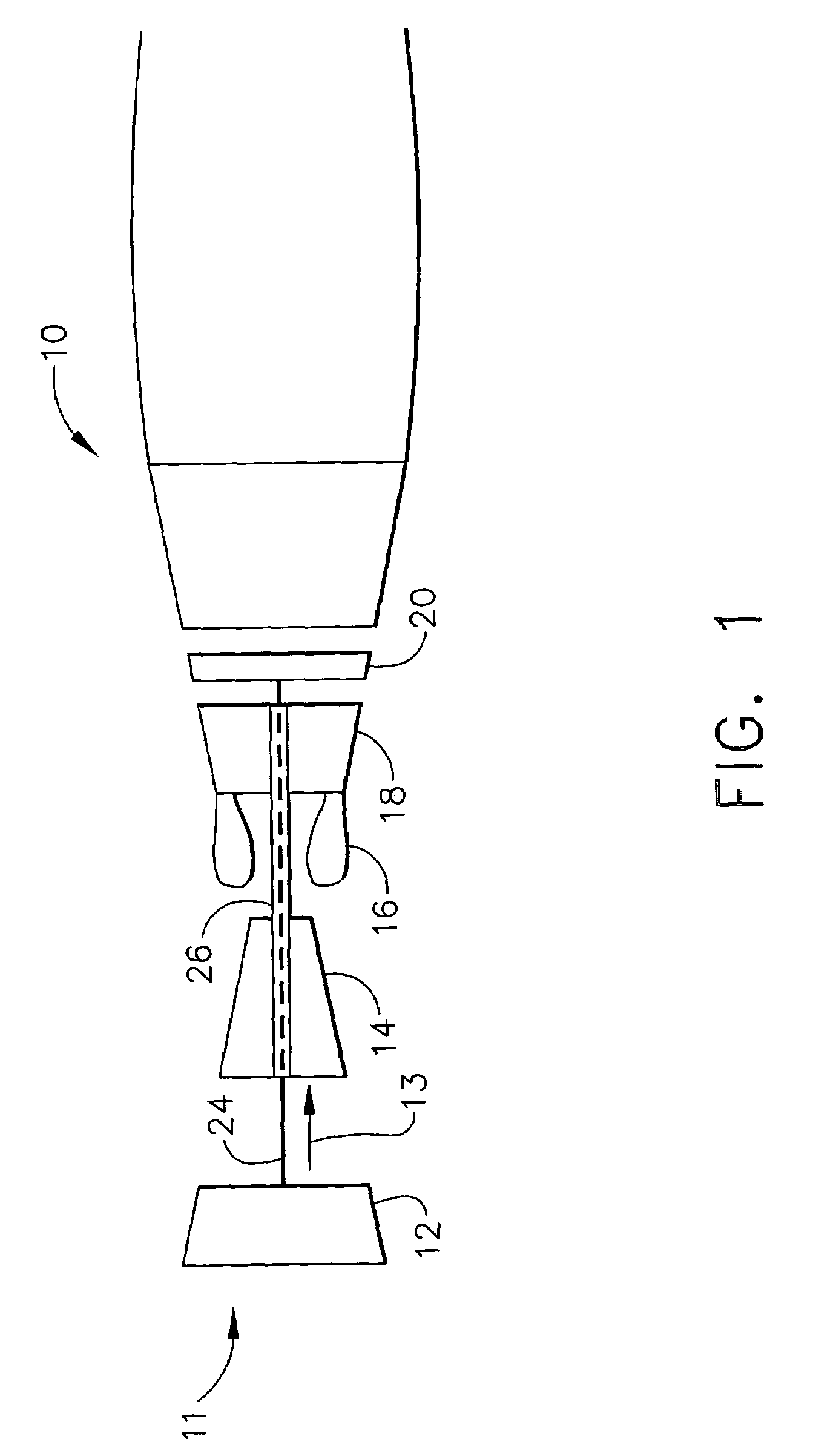
[0013]FIG. 1 is a schematic illustration of a gas turbine engine 10 including a low pressure compressor 12, a high pressure compressor 14, and a combustor assembly 16. Engine 10 also includes a high pressure turbine (HPT) 18, and a low pressure turbine 20 arranged in a serial, axial flow relationship. Compressor 12 and turbine 20 are coupled by a first shaft 24, and compressor 14 and turbine 18 are coupled by a second shaft 26. In one embodiment, engine 10 is a GE90 engine commercially available from General Electric Company, Cincinnati, Ohio.

[0014]In operation, air flows through low pressure compressor 12 from an upstream side 11 of engine 10 and compressed air 13 is supplied from low pressure compressor 12 to high pressure compressor 14. Compressed air 13 is then delivered to combustor assembly 16 where it is mixed with fuel and ignited. The combustion gases are channeled from combustor 16 to drive turbines 18 and 20.

[0015]In the exemplary embodiment, engine 10 is operable to powe...


PUM


Abstract

A method for assembling a rotor assembly for a gas turbine engine is provided. The engine includes an engine casing, a plurality of rotor blades, and at least one turbine shroud assembly. The method includes mounting a plurality of case segments together circumferentially to form the casing around the plurality of rotor blades and the at least one turbine shroud assembly, wherein each of the case segments includes at least two mounting flanges and a channel defined therebetween. The method also includes applying a thermal barrier coating to an inner surface of the channel and at least a portion of each mounting flange to facilitate maintaining axisymmetric running tip clearances between the plurality of rotor blades and the least one turbine shroud assembly during a cruise operation. The thermal barrier coating also facilitates controlling axisymmetric running tip clearances during a take-off operation such that an exhaust gas temperature and a specific fuel consumption is reduced.

Description

BACKGROUND OF THE INVENTION[0001]This invention relates generally to gas turbine engines, and more specifically to turbine casings used with gas turbine engines.[0002]At least some known gas turbine engines generally include, in serial flow arrangement, a high pressure compressor for compressing air flowing through the engine, a combustor in which fuel is mixed with the compressed air and ignited to form a high energy gas stream, and a high pressure turbine (HPT). The high pressure compressor, combustor, and high pressure turbine are sometimes collectively referred to as the core engine. Such gas turbine engines also may include a low pressure compressor, or booster, for supplying compressed air to the high pressure compressor.[0003]At least some known turbines include a rotor assembly including a plurality of rows of rotor blades. Each rotor blade extends radially outward from a blade platform to a tip. A plurality of shrouds couple together to form a flow path casing that extends ...

Claims


Application Information

Patent Timeline
Patent Type & Authority Patents(United States)
IPC IPC(8): F04D29/58
CPCF01D5/08F01D9/04F01D11/12F01D11/122F01D11/18F01D25/243Y02T50/67Y02T50/676Y02T50/60
Inventor HARRIS, DANIEL JOHN
Owner GENERAL ELECTRIC CO
Why Eureka
Try Eureka