Implant for osteosynthesis

Active Publication Date: 2007-07-24
STRYKER EURO OPERATIONS HLDG LLC
View PDF17 Cites 105 Cited by
  • Summary
  • Abstract
  • Description
  • Claims
  • Application Information

AI Technical Summary

Benefits of technology

[0003]It is one object of the invention to provide an implant for osteosynt

Problems solved by technology

The emigration of interlocking screws is critical and

Method used


Image

  • Implant for osteosynthesis
  • Implant for osteosynthesis
  • Implant for osteosynthesis

Examples


Example

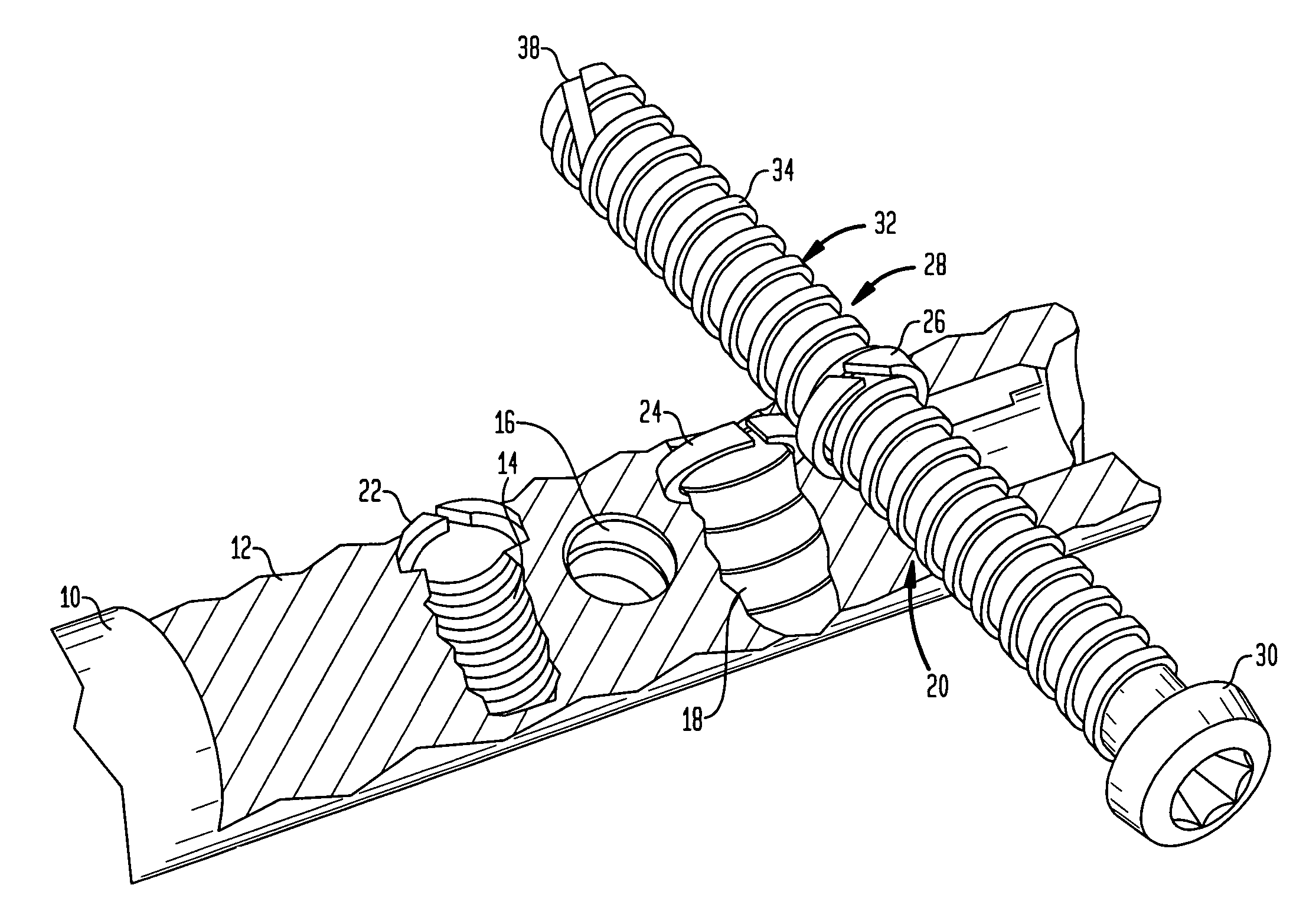
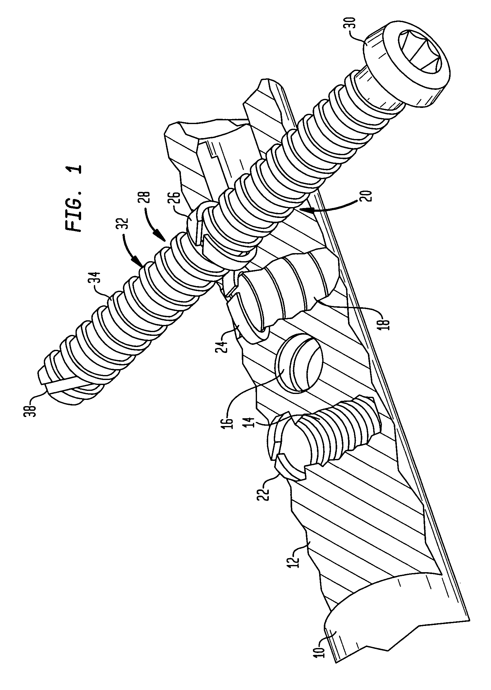
[0017]Referring to FIG. 1 there is shown a humeral nail 10 having four offset cross-bores and having a longitudinally sectioned proximal portion 12. As can be seen, the preferred proximal portion 12 is provided with four cross-bores 14, 16, 18 and 20 which, in the preferred embodiment are offset from each other in the axial and circumferential directions and are at an angle from the longitudinal axis 21 of nail 10. In the preferred embodiment, bores 14, 16, 18 and 20 are configured as threaded bores. FIG. 1 further shows that bores 14, 18 and 20 receive a securing ring 22, 24 and 26, respectively. If desired, bore 16 can also include a securing ring. These rings serve for securing an interlocking screw 28 which has a head 30 and a shank 32 with thread 34. In the preferred embodiment thread 34 is a cortical thread which is useful in ensuring a fixed seating in the bone without unnecessarily imposing a stress on the bone. The preferred thread 34 is a flat thread which threadably engag...


PUM


Abstract

An implant for osteosynthesis, for example a bone nail, has an implant body which has at least one bore with a threaded portion and a bone screw which engages the thread when it is threaded into a bone for the fixation of the implant body. The threaded bore has an annular groove the diameter of which is larger than the thread outer diameter, and which receives a ring of a deformable material with an inner diameter which is smaller than the outer diameter of the thread of the bone screw so that the ring extends partially into the bore.

Description

BACKGROUND OF THE INVENTION[0001]It is generally known to fix plates to bone by means of bone screws for the repair of bone fractures. Further, it is well known to configure bone screws for use with so-called interlocking nails for the care of fractures of tubular bones. Interlocking nails have cross-bores for the reception of bone screws or interlocking screws at both the distal and proximal nail ends. It is known to provide the bores with a thread for the reception of a bone screw. In most cases, the thread is a so-called cortical thread, i.e. a thread corresponding to the thread of the bone screw. This thread has the advantage that it impedes the postoperative migration of the bone screws.[0002]It is known to configure nails for the repair of humeral fractures as interlocking nails and to provide several cross-bores in the proximal portion of the interlocking nail which are offset from each other in the circumferential direction and extend obliquely to the axis of the nail, if re...

Claims


Application Information

Patent Timeline
IPC IPC(8): A61B17/58A61B17/72A61B17/76A61B17/86
CPCA61B17/72A61B17/7241A61B17/74A61B2017/8655
Inventor PRAGER, RONALDZANDER, NILS
Owner STRYKER EURO OPERATIONS HLDG LLC
Why Eureka
Try Eureka