Beam architecture for improving angular resolution

a beam structure and antenna technology, applied in the field of radar systems, can solve the problems of relatively high cost, relatively difficult design of radar systems for commercial products, and low so as to improve the angular resolution of antenna systems, improve radar performance, and improve angular resolution

Active Publication Date: 2007-07-24
VALEO RAYTHEON CO INC +1
View PDF31 Cites 24 Cited by
  • Summary
  • Abstract
  • Description
  • Claims
  • Application Information

AI Technical Summary

Benefits of technology

[0010]With this particular arrangement, a beam architecture which improves angular resolution of a radar system in a desired plane is provided. The improved angular resolution occurs by having each antenna beam cover a similar amount of area in space within a given coverage zone. In one embodiment, this is accomplished by narrowing end beams and / or broadening middle beams of a multi-beam antenna pattern. With this approach, an object traveling through each of the multiple beams produces a similar number of object detections in each beam as the object moves from beam to beam. In some applications, a system having a beam architecture in which beams cover a similar amount of space in a single plane can improve the overall azimuth resolution of a radar for any given number of azimuth beams (greater than two azimuth beams) while at the same time having a relatively small impact on cost and system complexity. In some automotive radar applications for example, the azimuth plane of an antenna corresponds to the plane of the road surface and the beam architecture described herein improves the overall azimuth resolution of the radar for any given number of azimuth beams. It should be appreciated, however, that the beam architecture of the present invention can benefit applications other than automotive radar applications. The beam architecture of the present invention can benefit any beam-limited application in which object detections of interest travel primarily in the radar's azimuth plane. It should be appreciated, of course, that the same principles described herein could be equally applied in the elevation plane of a radar. The invention is particularly useful in those applications in which the radar's minimum range (i.e. the minimum operational range at which the radar detects a target) is a relatively small fraction of its maximum range (i.e. the maximum operational range at which the radar detects a target) because such applications tend to have a need for beam architectures which result in significant target detections in each beam. Some of the specific automotive radar applications that can benefit from using this approach to radar beam architecture include but are not limited to blind spot detection, lane change, park slot measurement, cross-traffic warning, pre-crash, parking aid (including both front and back-up) and autonomous cruise control (ACC). In these applications, azimuth resolution is relatively important to system performance (since it is relatively important to have accurate information with respect to the location of objects). In some applications, the detections of interest are provided by objects travelling in a direction substantially parallel to the direction in which the vehicle containing the radar is travelling.
[0012]With this particular arrangement, a technique for improving angular resolution of an antenna system is provided. By having antenna beams with a beam shape selected such that a substantially equal number of detections can occur in each beam (for a constant velocity target) the angular resolution provided by the antenna system is increased for a given number of antenna beams. In one automotive radar system, this is accomplished by narrowing end beams and broadening middle beams of a multi-beam antenna system. In another embodiment, this can be accomplished by simply broadening middle beams of a multi-beam antenna system. In still another embodiment, this can be accomplished by simply narrowing end beams of a multi-beam antenna.
[0013]In accordance with a still further aspect of the present invention a method of operating a radar comprises providing a plurality of beams and combining beams to provide a shaped beam pattern for beam architecture) to match a particular detection environment. With this particular arrangement, a technique for improving radar performance in any application is provided by combining beams to provide a shaped beam pattern. By tracking a target with a shaped a beam pattern, a desired number of detections can be made to occur in each beam. By providing a shaped beam pattern in which a similar number of detections occur in each beam, radar resources (e.g. processing resources) can be used more efficiently and thus radar efficiency is improved. In some applications, this approach can also increase angular resolution since a similar number of target detections can occur in each beam.

Problems solved by technology

Such requirements make the design of radar systems for use in commercial products relatively challenging.
Among the design challenges is the challenge to provide an antenna system which meets the design goals of being high performance, low cost and compact.
In automotive radar systems, for example, cost and size considerations are of considerable importance.
One problem with these techniques, however, is that they typically result in relatively high cost systems.

Method used


Image

  • Beam architecture for improving angular resolution
  • Beam architecture for improving angular resolution
  • Beam architecture for improving angular resolution

Examples


Embodiment Construction

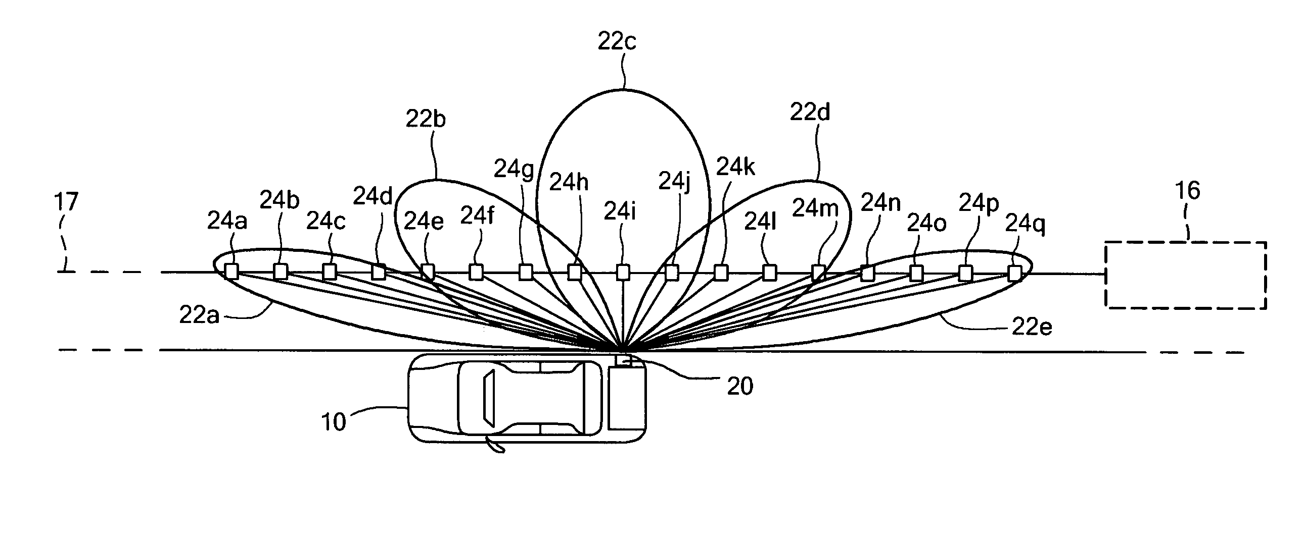
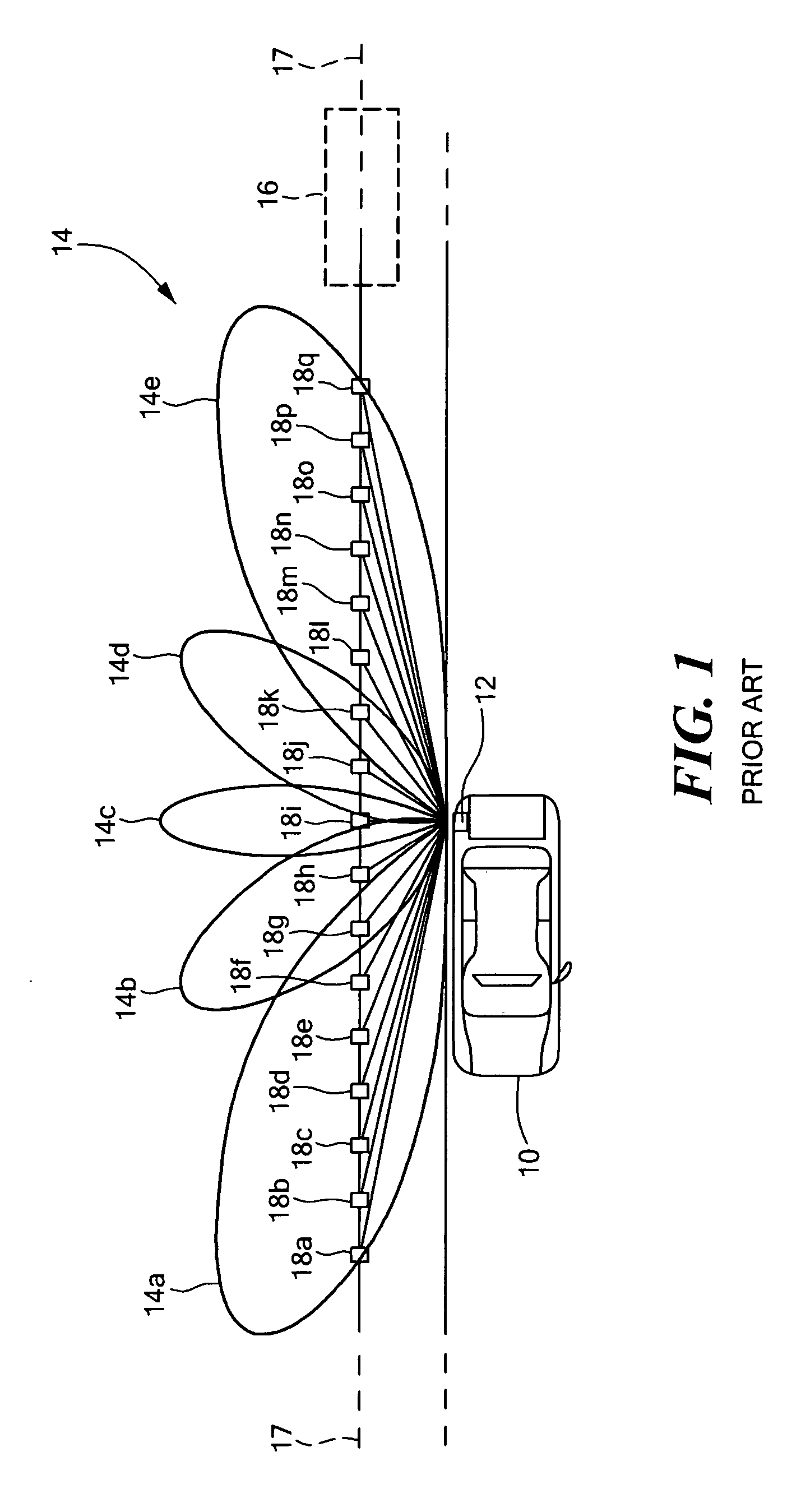
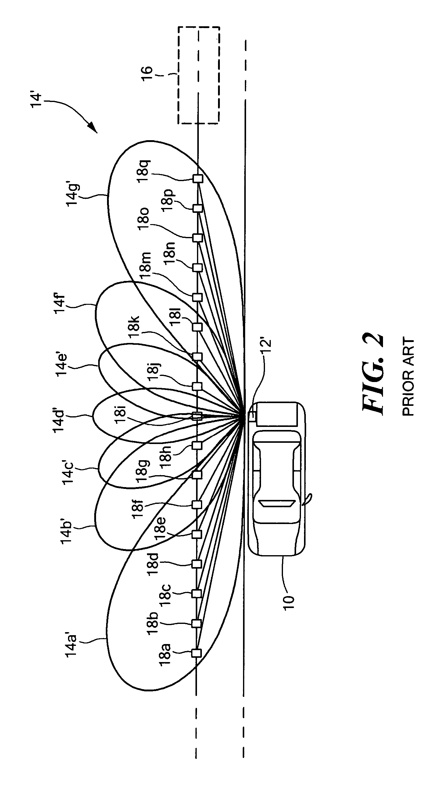
[0024]Referring now to FIG. 1, a vehicle 10 has a prior art automotive radar system 12 disposed on a side thereof. The automotive radar system 12 may, for example be provided as a side object detection system (SOD) also sometimes referred to as a blind spot detection system. A typical prior art automotive radar system, such as radar system 12, includes a planar array antenna capable of generating multiple antenna beams with five antenna beams (or more simply “beams”) 14a–14e being here shown. In automotive radar applications, the azimuth plane of the antenna often corresponds to the plane of the road surface

[0025]Radar 12 detects an object 16 moving along a path 17 which is parallel to the path of the vehicle 10 in which the radar 12 is disposed. The object 16, may for example, be another vehicle approaching and passing vehicle 10 in which the radar is disposed. The vehicle 16 can thus correspond to a vehicle in a lane in which is adjacent the vehicle 10 and thus the vehicle 16 is s...


PUM


Abstract

An automotive radar system includes a beamformer circuit and a beamcombiner circuit. The beamformer circuit forms a plurality of antenna beams at a plurality of beam ports. The beam combiner circuit receives the beams provided thereto from the beamformer circuit and combines the beams to provide a desired number of beams, with each of the beams having a desired beam shape. In one embodiment, the beamcombiner provides first and second end beams having a beamwidth which is less than a beamwidth of middle beams.

Description

CROSS-REFERENCE TO RELATED APPLICATIONS[0001]Not applicable.STATEMENTS REGARDING FEDERALLY SPONSORED RESEARCH[0002]Not applicable.FIELD OF THE INVENTION[0003]This invention relates generally to radar systems and more particularly to techniques for generating antenna beams for use in vehicle radar systems.BACKGROUND OF THE INVENTION[0004]As is known in the art, there is an increasing trend to include radar systems in commercially available products. For example, it is desirable to include radar systems in automobiles, trucks, boats, airplanes and other vehicles. Such radar systems are preferably compact and relatively low cost.[0005]Many products impose relatively strict requirements on both the physical size and operational performance of the radar system. Such requirements make the design of radar systems for use in commercial products relatively challenging. Among the design challenges is the challenge to provide an antenna system which meets the design goals of being high perform...

Claims


Application Information

Patent Timeline
Patent Type & Authority Patents(United States)
IPC IPC(8): G01S13/00
CPCH01Q1/3283H01Q25/00H01Q25/002G01S2013/9314G01S2013/9332G01S2013/9315
Inventor PLEVA, JOSEPH S.WIMMER, WILSON
Owner VALEO RAYTHEON CO INC
Why Eureka
Try Eureka