Image forming apparatus

a technology of image forming apparatus and forming tube, which is applied in the direction of electrographic process apparatus, instruments, optics, etc., can solve the problems of increasing apparatus cost, image failure or jitter generation, and unobservable color displacement, etc., and achieve the effect of reducing banding

Inactive Publication Date: 2007-07-24
CANON KK
View PDF10 Cites 2 Cited by
  • Summary
  • Abstract
  • Description
  • Claims
  • Application Information

AI Technical Summary

Benefits of technology

[0016]Accordingly, an object of the present invention is to provide an image forming apparatus capable of reducing the banding, which causes the vibration that generates the rotation and the stoppage of the rotary developing device without complicating the mechanism.

Problems solved by technology

In the case the positioning accuracy of the colors is low, specifically, in the case displacement of 50% or more with respect to the sub scanning pitch is generated, the unevenness or the color displacement can be observed visibly so that image failure called banding or jitter is generated in many cases.
However, due to the need of a special mechanism such as the detecting means and the correcting means, the apparatus cost is increased.

Method used


Image

  • Image forming apparatus
  • Image forming apparatus
  • Image forming apparatus

Examples


first embodiment

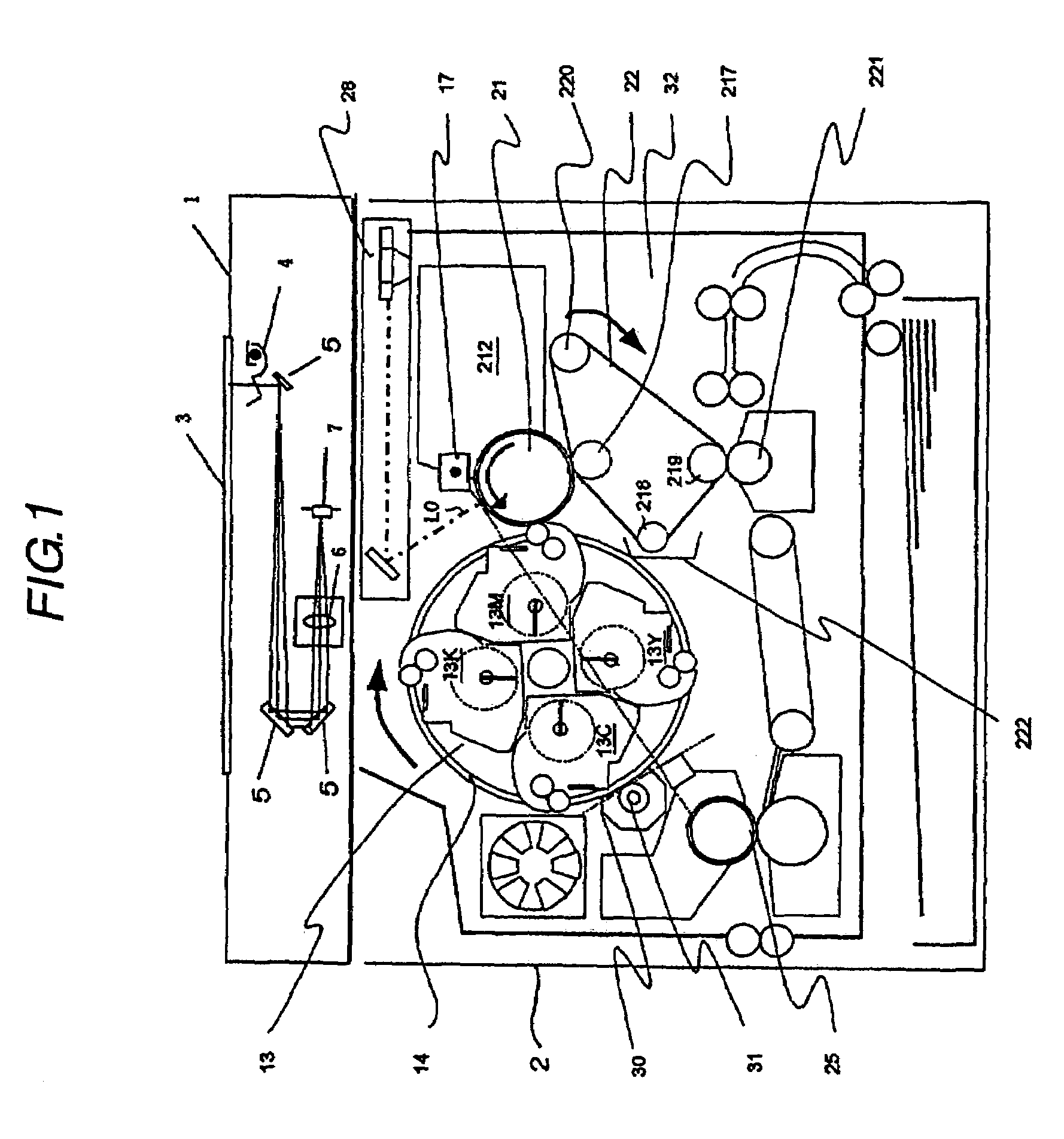
[0051]Hereinafter, a first embodiment of adopting the present invention to a one drum system color copying machine having one photosensitive member will be explained. FIG. 1 is a schematic configuration diagram of the entirety of a color copying machine according to the first embodiment.

[0052]Here, the entire configuration of the image forming apparatus will be explained first, and then, the driving system arrangement configuration of the rotary will be explained.

{Entire Configuration of the Image Forming Apparatus}

[0053]First, with reference to FIG. 1, the color image reading device (hereinafter, it is referred to as the “color scanner”) 1 and a color image recording device (hereinafter, it is referred to as the “color printer”) 2 comprising the color copying machine will be explained schematically.

[0054]The above-mentioned color scanner focuses the image of a document 3 onto a photoelectric conversion element 7 storing a color filter via an illumination lamp 4, a mirror 5 and a le...

second embodiment

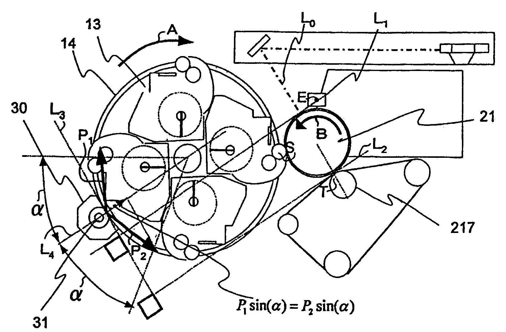
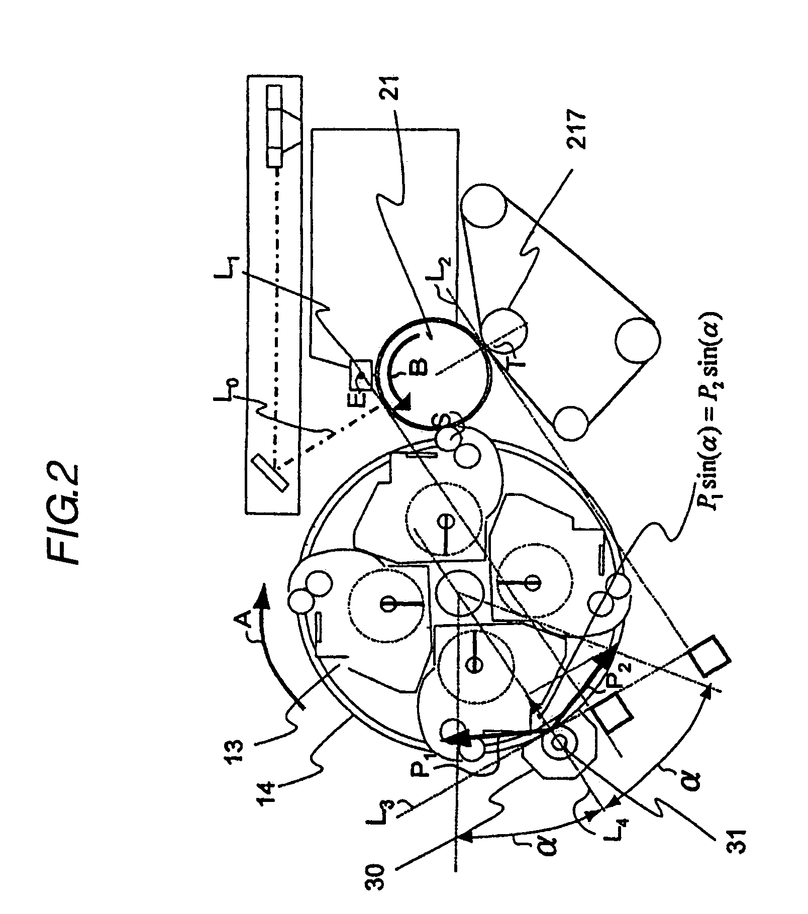
[0089]Next, an apparatus according to the second embodiment will be explained with reference to FIGS. 6 to 8. Since the basic configuration of the apparatus of this embodiment is same as that of the above-mentioned embodiment, redundant explanation is omitted, and the configuration characteristic of this embodiment will be described. The same numerals are applied to the members having the same functions as those of the above-mentioned embodiment.

[0090]Although the above-mentioned first embodiment has the configuration of reducing the vibration both at the time of starting and stopping the drive of the driving motor 30, according to this embodiment, the vibration of either one is further reduced. For example, in the case of a structure with the vibration transmitted hardly at the transfer position T, a configuration of reducing the vibration mainly at the exposing position E can be provided. On the contrary, in the case of a structure with the vibration transmitted hardly to the expo...

third embodiment

[0111]Next, an apparatus according to the third embodiment will be explained with reference to FIG. 10. Since the basic configuration of the apparatus of this embodiment is also same as that of the above-mentioned embodiment, redundant explanation is omitted, and the configuration characteristic of this embodiment will be described. Moreover, the same numerals are applied to the members having the same functions as those of the above-mentioned embodiment.

[0112]FIG. 10 shows an example with the driving motor 30 and the developing rotary 13 having the configuration of the friction transmission drive without using the gear drive. The pinion of the driving motor 30 and the pinion of the rotary are provided with a metal with the anti sliding treatment of the ceramic coating as the drive transmitting means. In FIG. 10, the numeral 35 is a friction ring provided in the developing rotary 13, 36 a friction pinion provided in the driving motor 30, and N the force needed for the drive transmis...


PUM


Abstract

The present invention relates to an image forming apparatus comprising: an exposing means and a developing means. The developing means comprises a plurality of developing devices, a rotating member rotatable while supporting the plurality of the developing devices, and a driving means for the rotation drive of the rotating member for selectively moving the plurality of the developing devices to the developing position such that the driving means transmits driving force to the rotating member via a gear at a drive transmitting position. An angle θe(°) formed by a straight line linking the rotation center of the rotating member and the drive transmitting position and the tangent of the image bearing member at an exposing position in the image bearing member moving direction satisfies the following relationship with the premise that an pressure angle of the gear is α(°) and the image bearing member rotating direction is positive: −α≦θe≦α.

Description

BACKGROUND OF THE INVENTION[0001]1. Field of the Invention[0002]The present invention relates to an image forming apparatus such as a copying machine, a facsimile and a printer. More specifically, it relates to an image forming apparatus comprising a rotatable developing device for developing a plurality of colors, and a transferring means as an intermediate transfer member for forming toner images of a plurality of colors on a photosensitive member and transferring the toner images on the photosensitive member or a rotatable transfer drum supporting a recording medium for transferring the toner images on the photosensitive member to the recording medium.[0003]2. Related Background Art[0004]Conventionally, as the configuration of an apparatus for forming a multiple color image according to an electrophotographic system, a multiple color image is obtained by forming a latent image by the selective exposure on an image bearing member (hereinafter it is referred to as the “photosensiti...

Claims


Application Information

Patent Timeline
Patent Type & Authority Patents(United States)
IPC IPC(8): G03G15/01G03G15/00G03G15/06
CPCG03G15/0173G03G15/0121G03G2215/0177
Inventor YOKOTA, MASAHIKONAGASE, TETSUYANAKAHATA, HIROSHIKUDO, TOSHIHIKOFUJIWARA, YUKIHIRO
Owner CANON KK
Why Eureka
Try Eureka