

Light emitting device
a technology of light emitting device and light source, which is applied in the direction of lighting and heating apparatus, mobile visual advertising, instruments, etc., can solve the problems of low design quality and short luxury
- Summary
- Abstract
- Description
- Claims
- Application Information
AI Technical Summary
Benefits of technology
Problems solved by technology
Method used
Image

Examples
first embodiment
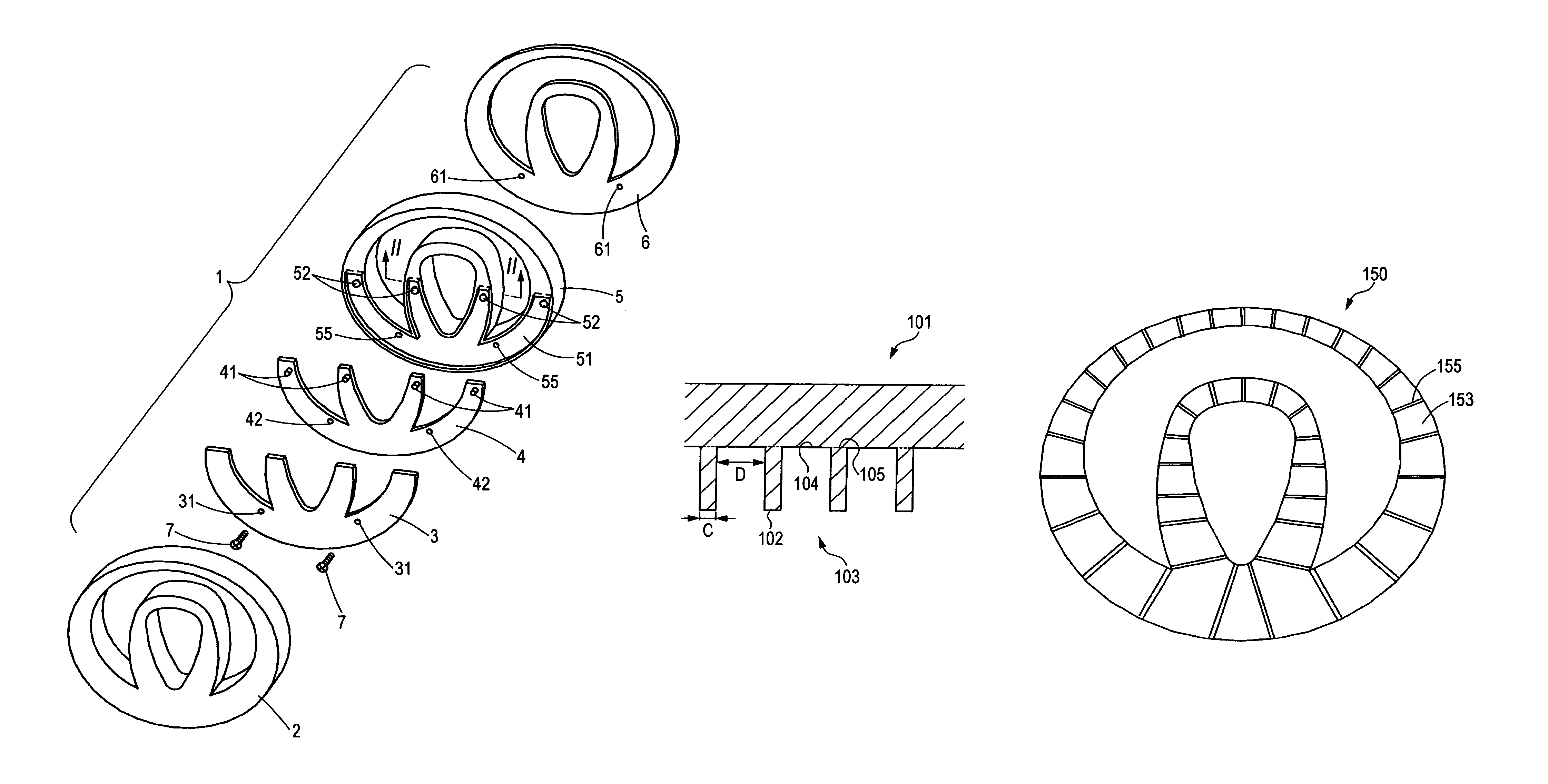
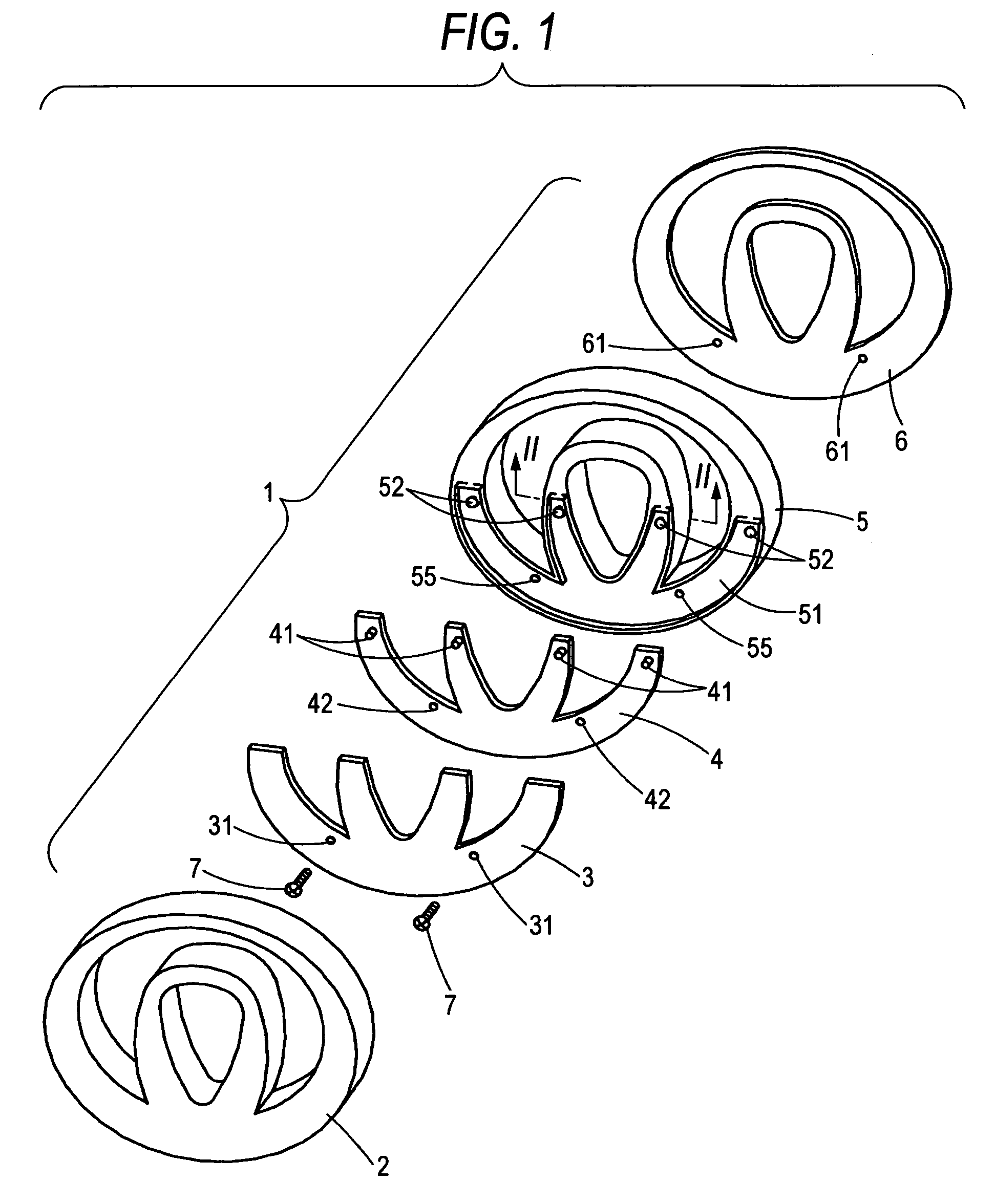
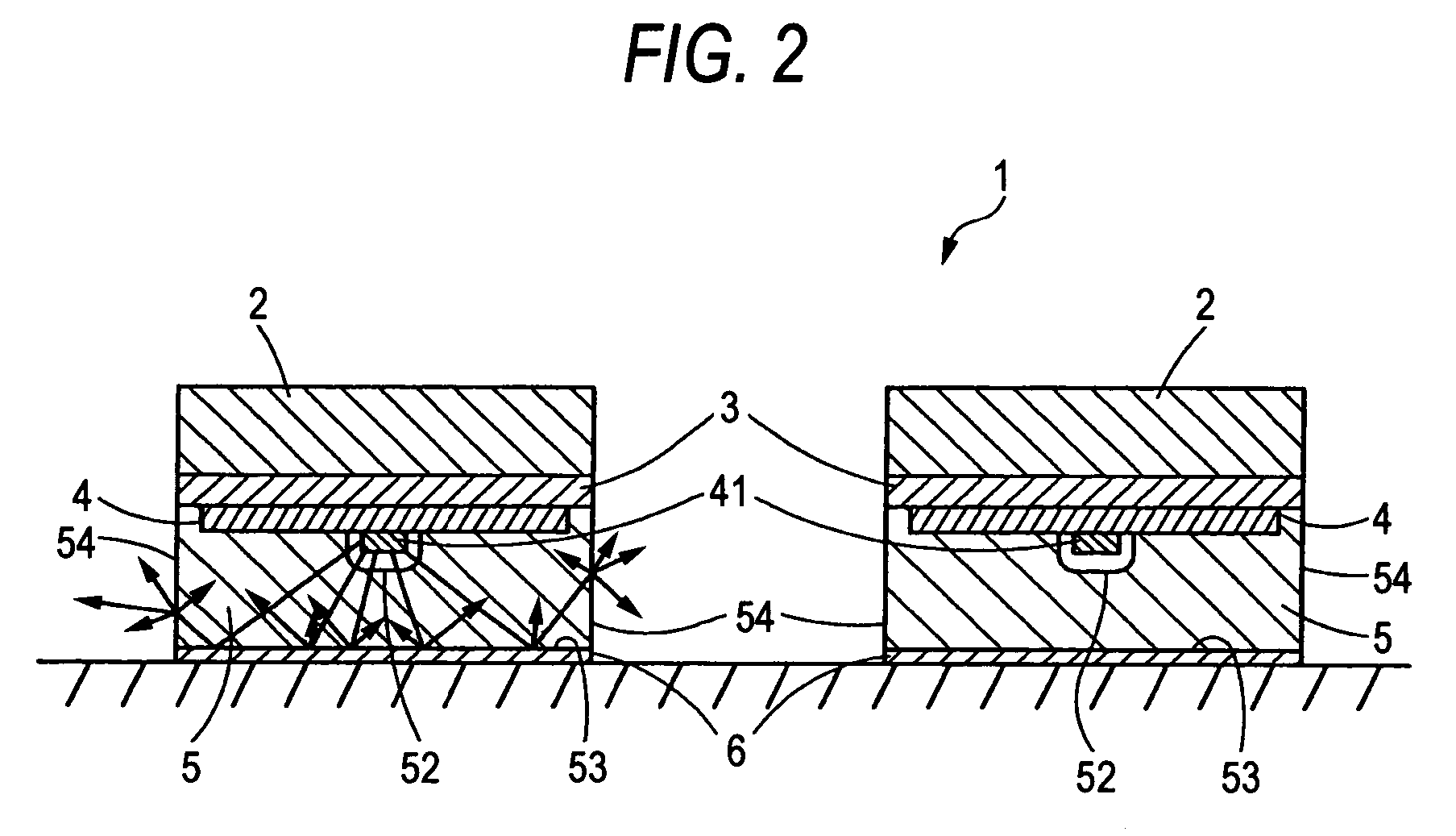
[0064]In FIG. 1 is shown an exploded perspective view of an emblem light emitting device 1 in a first embodiment of the invention. In FIG. 2 is shown a vertical cross-sectional view taken along line II-II of the emblem light emitting device 1 in FIG. 1. In FIG. 3 is shown a view of a light guide plate 5 as viewed from above. The emblem light emitting device 1 is to be attached to a vehicle body at a rear thereof (e.g. on a trunk lid). As shown in FIG. 1, the emblem light emitting device 1 is arranged with a cover 3, a substrate 4 and a light guide plate (light guide) 5 in this order in back of the mark body 2. Incidentally, numeral 4 is a white double-sided tape.
[0065]The mark body 2 is in a plan form having two ellipses different in size are fused together in a part thereof. The mark body 2, of ABS resin, has an observation surface (surface) covered with plating. The substrate 4 has a plan form analogous to and somewhat smaller than the lower half in plan form of the mark body 2. T...
second embodiment
[0069]In FIG. 4 is shown an exploded perspective view of an emblem light emitting device 10 in a second embodiment of the invention. In FIG. 5 is shown a vertical cross-sectional view taken along line V-V in FIG. 4. Incidentally, in the figures, the same members as those of the light emitting device 1 are attached with the same references, to omit the explanations thereof. In a light guide plate 50 of this embodiment, embossing has been done to a backside 530 of the light guide plate 50 of this embodiment. In the emblem light emitting device 10 having the light guide plate 50, the LED 41 light entered the light guide plate 50 is diffuse reflected by the embossed backside 530.
[0070]Accordingly, because the backside 530 provides the equivalent effect to the backside 53 of emblem light emitting device 1 applied with the white double-sided tape 6, the emblem light emitting device 10 can obtain the similar light-emission mode to the emblem light emitting device 1.
[0071]Although the cover...
third embodiment
[0072]In FIG. 10 is shown an exploded perspective view of an emblem light emitting device 110 in a third embodiment of the invention. The emblem light emitting device 110 is to be attached to a body rear of a vehicle (e.g. on a trunk lid). As shown in FIG. 10, the emblem light emitting device 110 is arranged with a cover 130, a substrate 140 and a light guide plate (light guide) 150 in this order in back of the mark body 2. Incidentally, numeral 160 is a double-sided tape.
[0073]The mark body 120 is in a plan form having two ellipses different in size fused together in a part thereof. The mark body 120, of ABS resin, has an observation surface (surface) covered with plating. The substrate 140 has a plan form analogous to and somewhat smaller than the lower half in plan form of the mark body 120. The substrate 140 is mounted with four LEDs 141 on an opposite surface to the mark body 120, in regions close to the upper ends of the four protrusions. The LEDs 140 are white-light LEDs of t...
PUM
 Abstract
Description
Claims
Application Information