Serializer/deserializer circuit for jitter sensitivity characterization

a serializer and jitter sensitivity technology, applied in the field of serial communication data transfer, can solve the problems of exacerbated situation, limited ability of standard characterization test equipment to generate high frequency jitter data, and general impracticality of evaluating in-situ quality

Inactive Publication Date: 2007-07-31
INT BUSINESS MASCH CORP
View PDF5 Cites 31 Cited by
  • Summary
  • Abstract
  • Description
  • Claims
  • Application Information

AI Technical Summary

Benefits of technology

[0017]According to the present invention there is described an improved serializer / deserializer (SERDES) circuit having built-in self-test capabilities that is configured to perform jitter sensitivity characterization of the clock and data recovery (CDR) circuit placed in the receiving part thereof. In essence, in the diagnostic mode, a perturbation is added to the serial data stream at the serializer output. Typically, the perturbation generator circuit includes a variable delay element. Then, the perturbed serial data stream is looped back to the CDR circuit. A dedicated circuit coupled to the perturbation generator circuit and to the deserializer circuit analyzes the recovered data to characterize the jitter sensitivity of the CDR circuit to any incoming data stream jitter. Moreover, the perturbed data stream can be transmitted to a distant SERDES circuit before it is looped back to the CDR circuit. In this case, in the distant SERDES circuit, the receiver output is directly connected to the driver input. By comparing the jitter sensitivity with and without using the transmission lines, one can easily and in situ characterize the amount of jitter added by the transmission lines. In addition, by continuously modifying the output delay of the serial data stream, i.e. the amplitude and the frequency of the perturbation, a perturbed serial data stream may be generated, closely approximating the actual jittered data. When such a perturbed data stream is recovered through the deserializer, it is possible to characterize the sensitivity of the CDR circuit to the jitter frequency.
[0019]Therefore, verification of the jitter tolerance performance of the CDR circuit placed in a serializer / deserializer circuit may be accomplished at the manufacturing level. In addition, this jitter sensitivity characterization can be performed at each power-on or initiated at any time on request for self diagnostic purposes. Admittedly, the jitter tolerance is the most critical CDR circuit specification to be met and also is the most important parameter to maintain the Bit Error Rate (BER) performance at the receiving side (CDR and DES circuits). Finally, the test coverage is improved and consequently the product quality delivered to the customer.

Problems solved by technology

The jitter tolerance of the CDR circuit is usually not characterized in-situ as it requires a jittered data generator, a specialized and expensive piece of characterization equipment.
In addition, when such characterization is performed before delivery to the customer, it usually involves a few samples of the total order because of the time required to complete it.
Lastly, without a jittered data generator, it is generally impractical to evaluate in-situ the quality of a particular physical link between the local and distant serializer / deserializer circuits or to determine if the CDR circuit is still working as specified.
The capabilities of standard characterization test equipment to generate high frequency jittered data is typically limited to a small percentage of the data transmission rate.
This situation is exacerbated for the test equipment used in the manufacturing lines, because they are usually not able to run at full speed.
However the system and method described therein are limited to the functional test and cannot be used to assess and characterize the jitter immunity of the CDR circuit.
However, this reference does not address the sensitivity of a CDR circuit to jittered data.
Moreover, there is no teaching as to a method of predicting whether data will be lost through the CDR circuit or whether the latter can recover the data with a sufficient margin.

Method used


Image

  • Serializer/deserializer circuit for jitter sensitivity characterization
  • Serializer/deserializer circuit for jitter sensitivity characterization
  • Serializer/deserializer circuit for jitter sensitivity characterization

Examples


Embodiment Construction

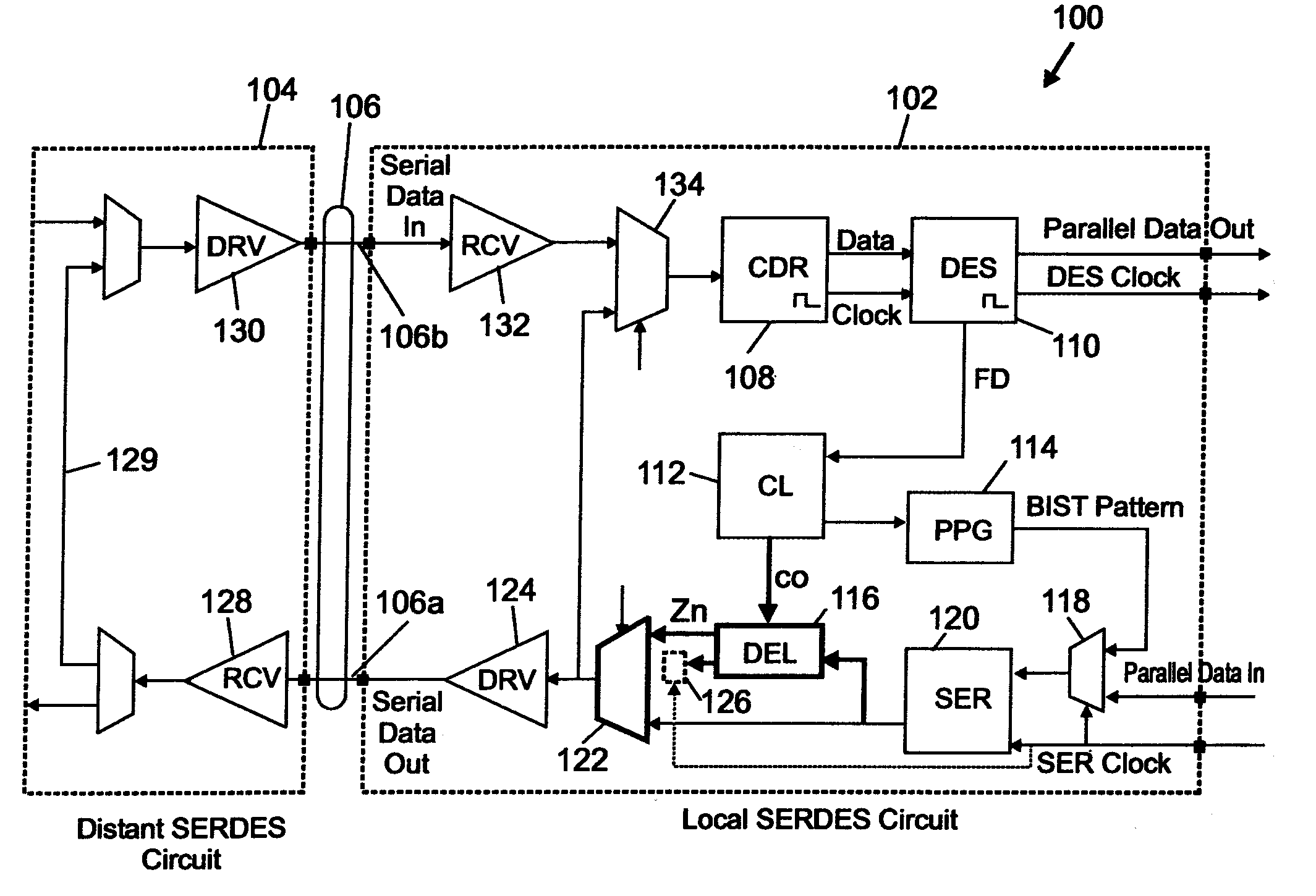
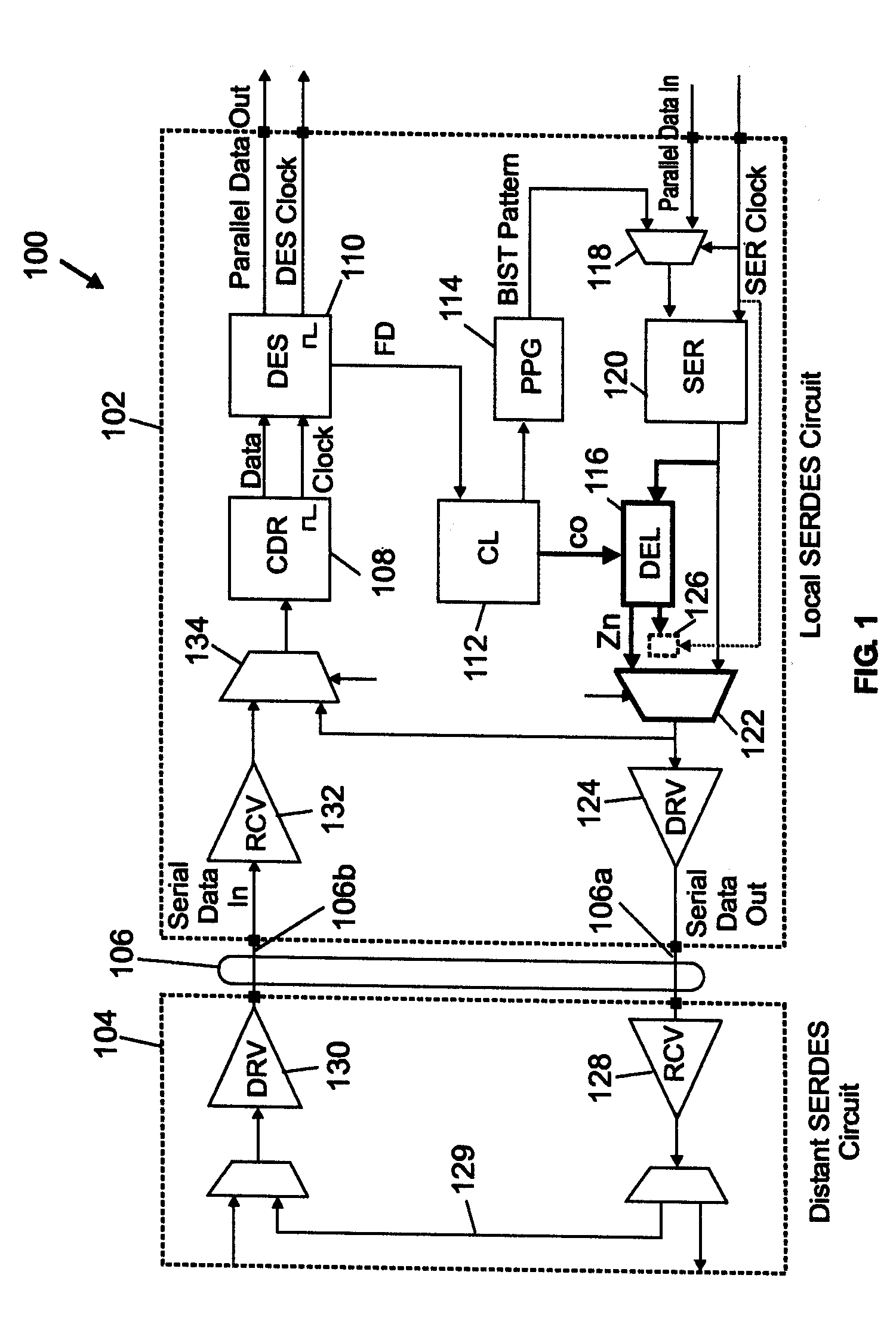
[0030]A telecommunication system 100 includes a local SERDES circuit 102, improved according to the present invention, and a distant SERDES circuit 104 is shown in FIG. 1. SERDES circuits 102 and 104 are connected by two physical transmission lines forming the link represented by bus 106 that transports the serial data streams for data exchange between the two components. In essence, the SERDES circuit 102 of the present invention represents an improvement over prior art SERDES circuits having built in self-test (BIST) capabilities. See for example FIG. 2 of United States Patent Application Publication No. 2001 / 016929 A1 noted above.

[0031]The receiving side of the local SERDES circuit 102 is constructed around the clock and data recovery (CDR) circuit 108 (receives the serial data from the distant SERDES circuit 104) and the DES circuit 110 which are connected in series. The CDR circuit 108 generates recovered serial data and clock. The DES circuit 110 transforms these recovered ser...


PUM

PropertyMeasurementUnit
timeaaaaaaaaaa
frequencyaaaaaaaaaa
data transmission rateaaaaaaaaaa

Abstract

Disclosed herein is an improved serializer / deserializer (SERDES) circuit (102) having built-in self-test capabilities that is configured to perform an in-situ jitter sensitivity characterization of the clock and data recovery (CDR) circuit (108). To that end, a delay perturbation is added to the serial data stream at the serializer (120) output, typically using a variable delay (DEL) line (116). Then, the perturbed serial data stream is looped back to the CDR circuit. A dedicated circuit in the control logic (112) coupled to the DEL line and the deserializer circuit (110) analyzes the recovered data to characterize the sensitivity of the CDR circuit to the jitter frequency. By continuously modifying the output delay of said serial data stream, i.e. the amplitude and the frequency of the perturbation, one can generate a perturbed serial data stream, very close to the real jittered data.

Description

BACKGROUND OF INVENTION[0001]1. Field of the Invention[0002]The present invention relates to high speed serial communications data transfers between integrated circuits or systems and more particularly to an improved serializer / deserializer circuit having built-in self-test capabilities that is configured for jitter sensitivity characterization of the clock and data recovery circuit. A method for characterizing jitter sensitivity is also disclosed.[0003]2. Background of the Invention[0004]In the field of serial communications data transfers between integrated circuits or systems, it is common practice to exchange data between two telecommunications systems, one being referred to as the local SERDES circuit and the other as the distant SERDES circuit, each incorporating a serializer / deserializer (SERDES) function. In each SERDES circuit, the receiving part is usually provided with a clock and data recovery (CDR) circuit connected in series with the deserializer circuit that is in cha...

Claims


Application Information

Patent Timeline
Patent Type & Authority Patents(United States)
IPC IPC(8): G01R31/28G01R31/317G06K5/04G11B5/00G11B20/20H03M9/00H04L1/20H04L1/24H04Q11/04
CPCG01R31/31709G01R31/31715G01R31/31725H03M9/00H04L1/205H04L1/243H04L1/244H04J2203/0062H04J2203/0089
Inventor BONNEAU, DOMINIQUE P.HAUVILLER, PHILIPPEVALLET, VINCENT
Owner INT BUSINESS MASCH CORP
Why Eureka
Try Eureka