

Condensed water storing apparatus of a dryer
a drying machine and condensed water technology, applied in the field of drying machines, can solve the problems of wet floors, excessive heavy weight of the drying machine, and flow of condensed water, and achieve the effect of reducing unnecessary work and being easy to opera
- Summary
- Abstract
- Description
- Claims
- Application Information
AI Technical Summary
Benefits of technology
Problems solved by technology
Method used
Image

Examples
Embodiment Construction
[0031]Hereinafter, a specific embodiment of the present invention is described in detail with reference to the accompanying drawings. However, the spirit of the invention is not limited to the embodiment, but retrograde embodiments and other embodiments within the scope of the invention may be proposed by adding, changing or deleting any component.
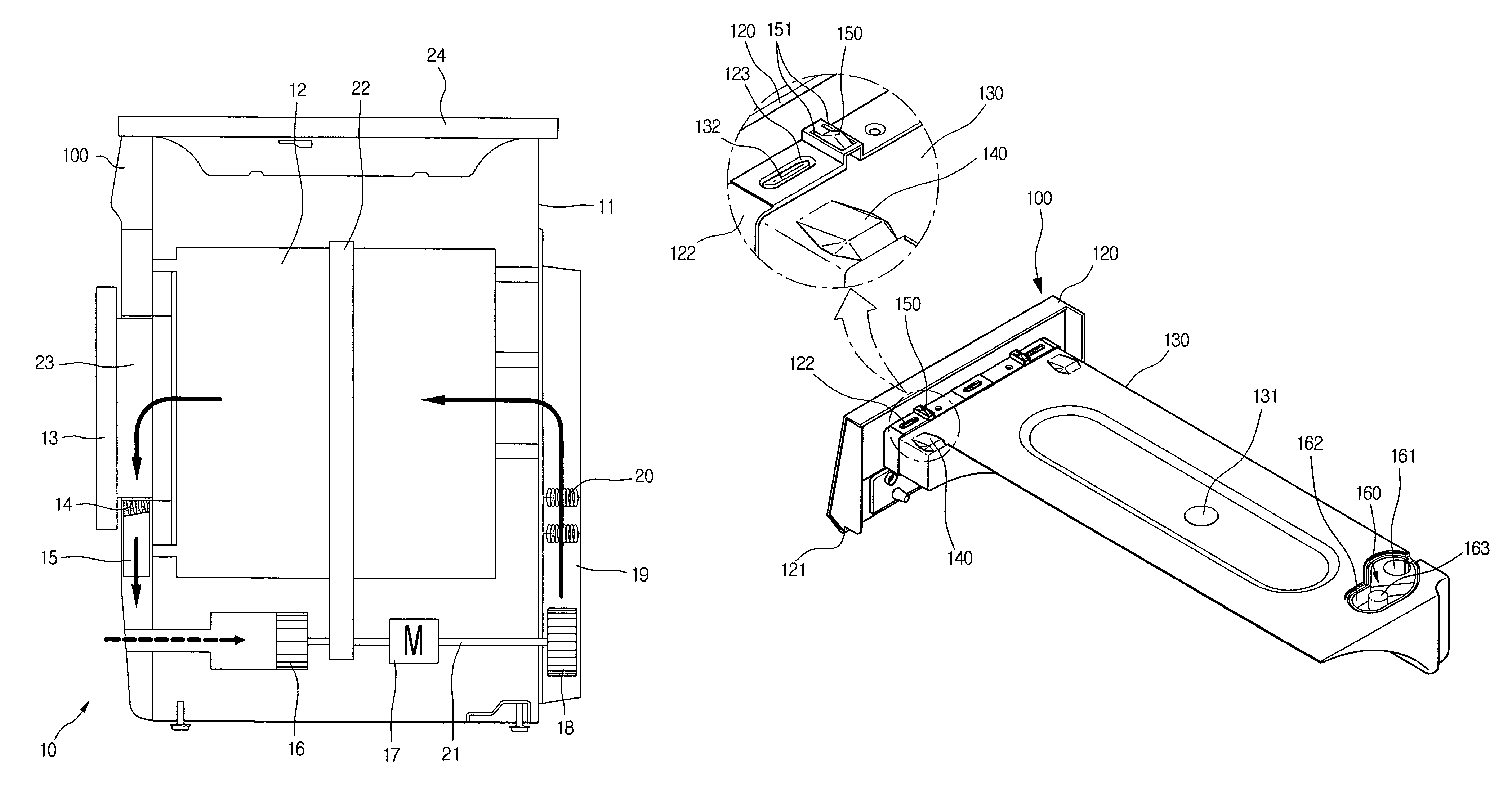
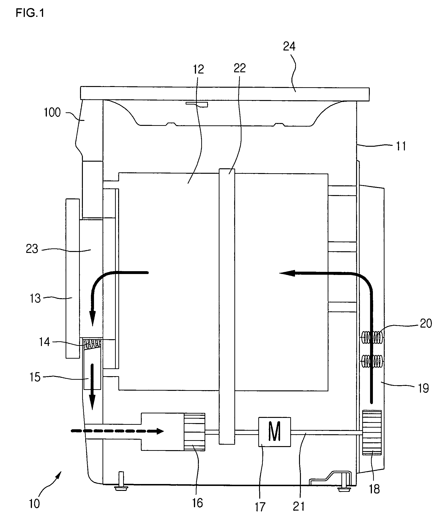
[0032]FIG. 1 is a sectional view showing a dryer having a condensed water storing apparatus according to the spirit of the present invention.
[0033]Referring to FIG. 1, the dryer 10 having the condensed water storing apparatus according to the present invention includes a cabinet 11 configuring an appearance of the dryer, a cylindrical drum 12 received in the cabinet 11, a top plate 24 seated on the top of the cabinet 11 to protect the dryer from a falling matter, a drawer 100 inserted to an upper portion of the front of the cabinet 11 to store condensed water generated during a drying procedure, a door 13 for controlling opening / closing of...
PUM
 Abstract
Description
Claims
Application Information