Check patentability & draft patents in minutes with Patsnap Eureka AI!

Panels comprising an interlocking snap-in profile

Inactive Publication Date: 2007-08-07
M KAINDL
View PDF24 Cites 203 Cited by
  • Summary
  • Abstract
  • Description
  • Claims
  • Application Information

AI Technical Summary

Benefits of technology

[0017]Since the connection between the two panels, in the initial position, exhibits play, it is not necessary to comply with the high degree of production accuracy mentioned at the beginning in order to join them. Joining can be successfully achieved even if the boards are slightly warped.
[0021]Thus, the desired goals are realized, namely a reliable connection without the use of adhesives which is not affected by inaccuracies in production on the one hand, and avoidance of play in the connecting joint on the other hand.

Problems solved by technology

In the final position, therefore, the aforementioned shifting as a result of a play is no longer possible.

Method used


Image

  • Panels comprising an interlocking snap-in profile
  • Panels comprising an interlocking snap-in profile
  • Panels comprising an interlocking snap-in profile

Examples


Embodiment Construction

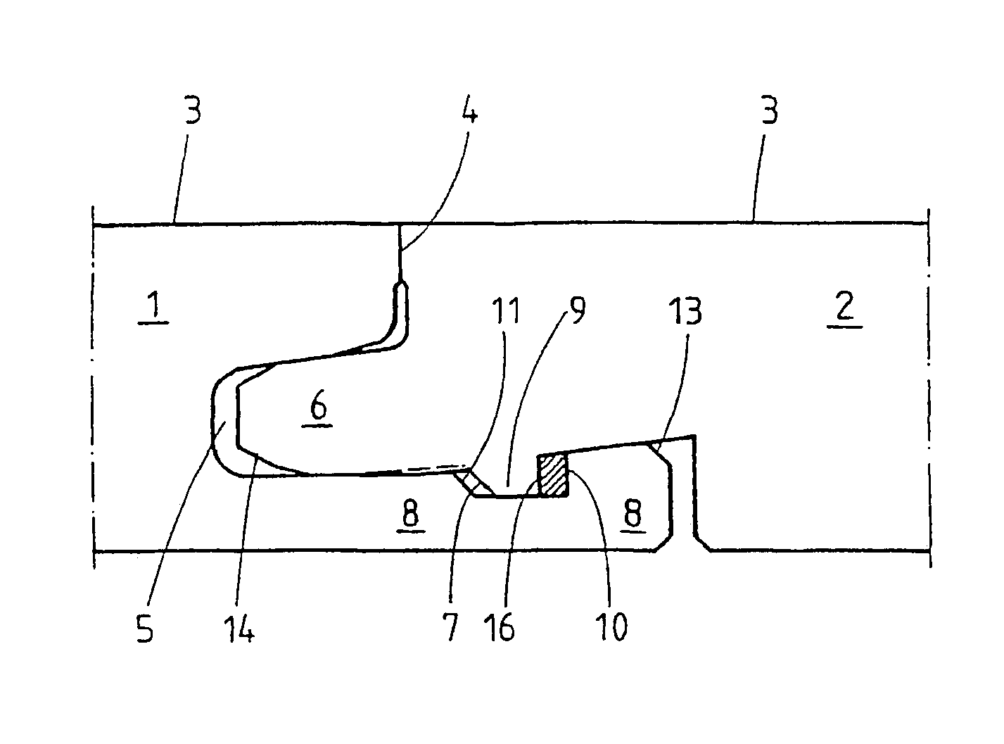
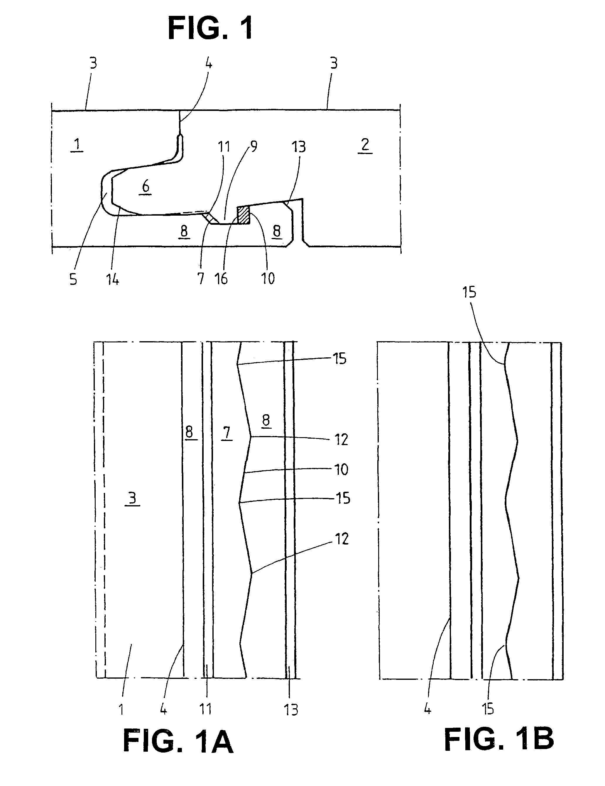
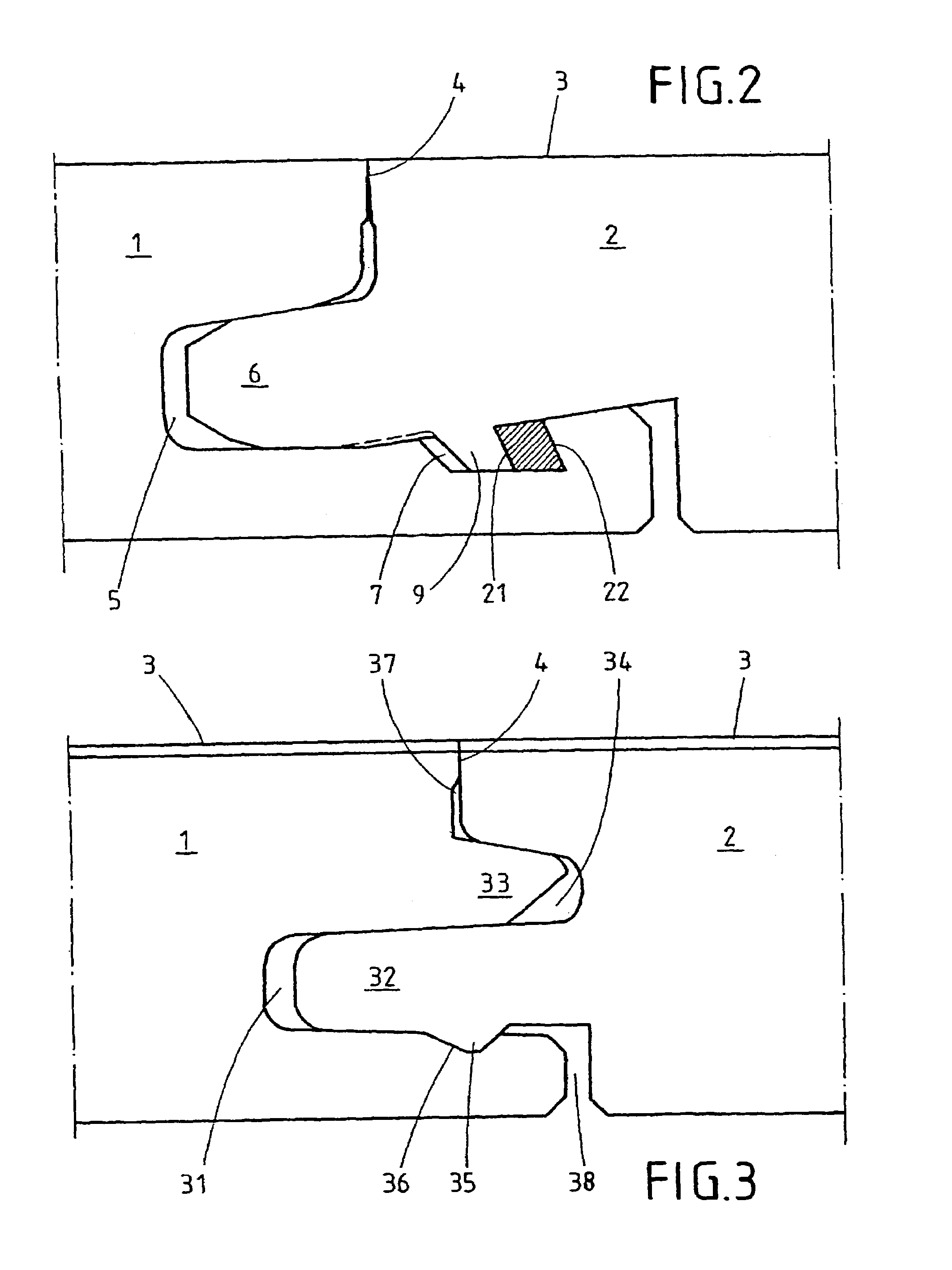
[0028]In one embodiment of the invention, a board has, at the sides, a groove and / or a tongue. The tongue protrudes in a lateral direction, parallel to the surface of the board. The groove has, e.g., been milled in laterally, parallel to the surface of the board. By pushing a tongue of a first board into the aforementioned groove of a second board, the two boards are interconnected in the known manner so that they are interlocked, in a vertical direction relative to the surface, because of positive fit.

[0029]The boards have further locking elements which make possible the connection by positive fit, in a parallel direction relative to the surface as well as in a vertical or perpendicular direction relative to the connecting joint. In general, this is a second groove which has been, e.g. milled in a vertical direction to the surface. The second groove may be provided at the bottom side of a board or in the first-mentioned groove. From FIG. 1 of printed publication WO 94 / 26999, it is ...


PUM


Abstract

Panels or boards comprise laterally mounted locking elements that can be inter-connected laterally in a positive fit, without the use of adhesive. The locking elements are designed to be connected in an initial position in which the panels are interlocked at least in one direction in a positive fit and a certain amount of play occurs in the common joint of the two panels. The panels may then be shifted, in a parallel direction relative to the common joint, to final position in which there is no play in the common joint and the panels are interconnected without the use of adhesive.

Description

CROSS-REFERENCES TO RELATED APPLICATIONS[0001]The present application is a national phase of International Application No. PCT / EP01 / 12359, filed Oct. 25, 2001, which claims the priority of German Patent Application No. 201 09 840.7, filed Jun. 17, 2001.BACKGROUND OF THE INVENTION AND RELATED ART[0002]The invention relates to boards having laterally mounted locking elements as well as to installing them.[0003]A board of the kind mentioned at the beginning is known from printed publication EP 090 6994 A1 as “panel”. As a rule, a panel is an oblong, thin board which can be connected laterally with further panels, i.e. on its longitudinal and transverse sides, e.g. by means of tongues and grooves. Panels connected in this manner are being used particularly as floor coverings or wall coverings.[0004]The connected panels are, for example, put together to form a floor covering known as laminate flooring. The panels comprise a carrier board made from a derived timber product as well as a de...

Claims


Application Information

Patent Timeline
IPC IPC(8): E04B2/32E04F15/04
CPCE04F15/04E04F2201/0115E04F2201/0123E04F2201/0153E04F2201/023E04F2201/025E04F2201/07
Inventor KONZELMANN, KARL-HEINZMOEBUS, MAIK
Owner M KAINDL
Features
  • R&D
  • Intellectual Property
  • Life Sciences
  • Materials
  • Tech Scout
  • Unparalleled Data Quality
  • Higher Quality Content
  • 60% Fewer Hallucinations
Learn More