

Mechanical in line timer valve
a timer valve and mechanical technology, applied in the field of water valve timers, can solve the problems of limited life of timers, limited effective range of timers, electrical devices with some safety risks,
- Summary
- Abstract
- Description
- Claims
- Application Information
AI Technical Summary
Benefits of technology
Problems solved by technology
Method used
Image

Examples
Embodiment Construction
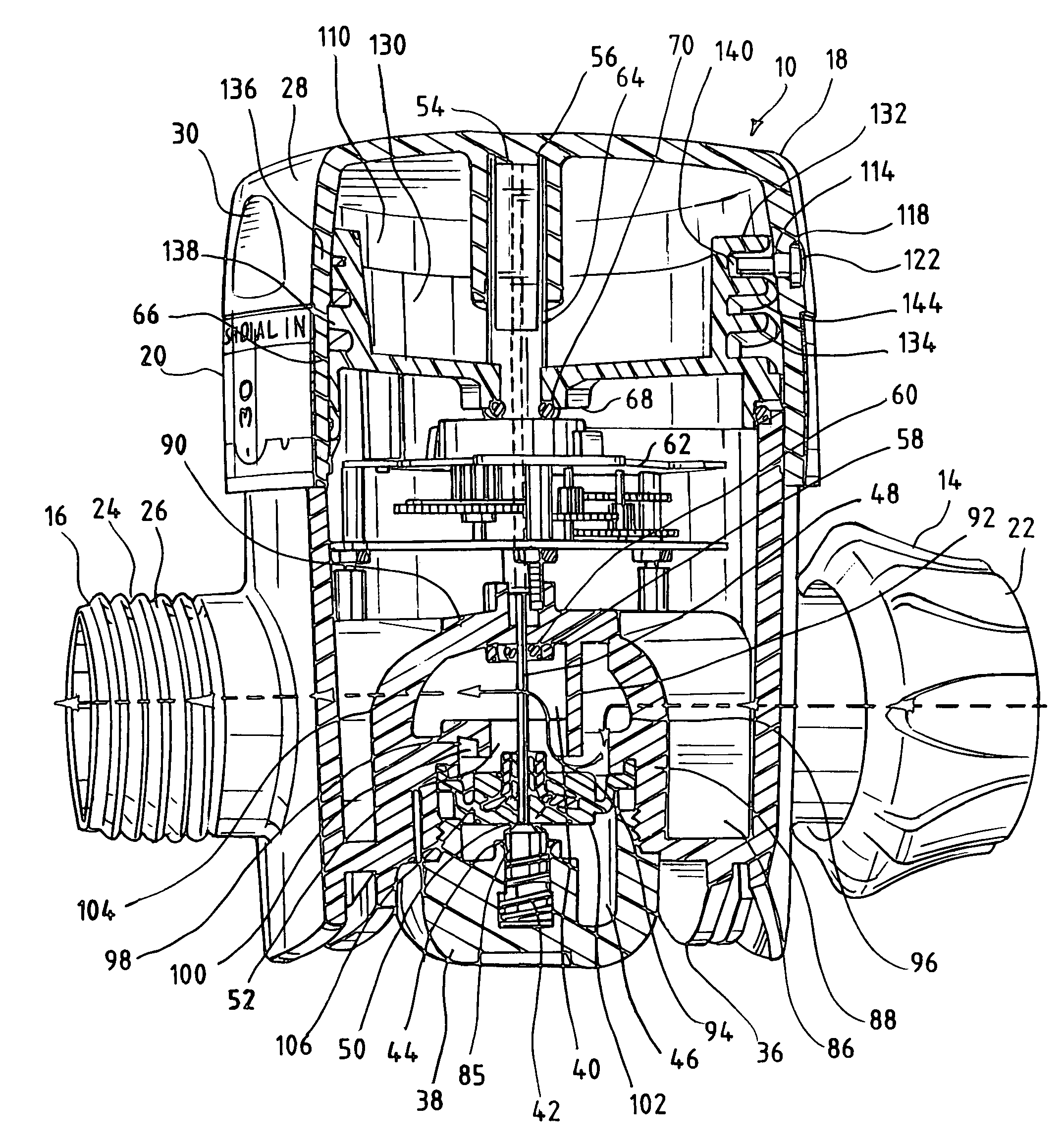
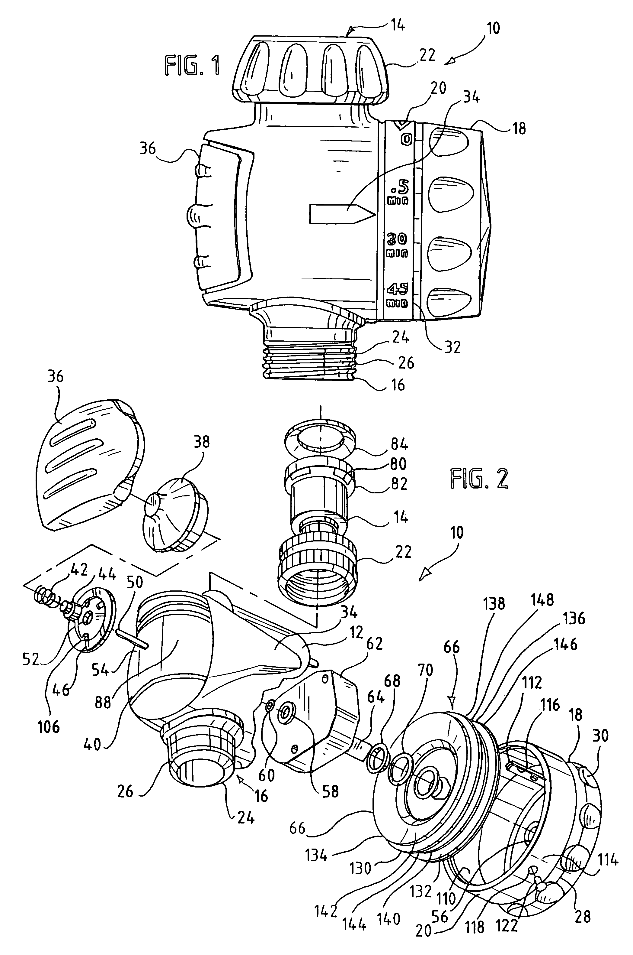
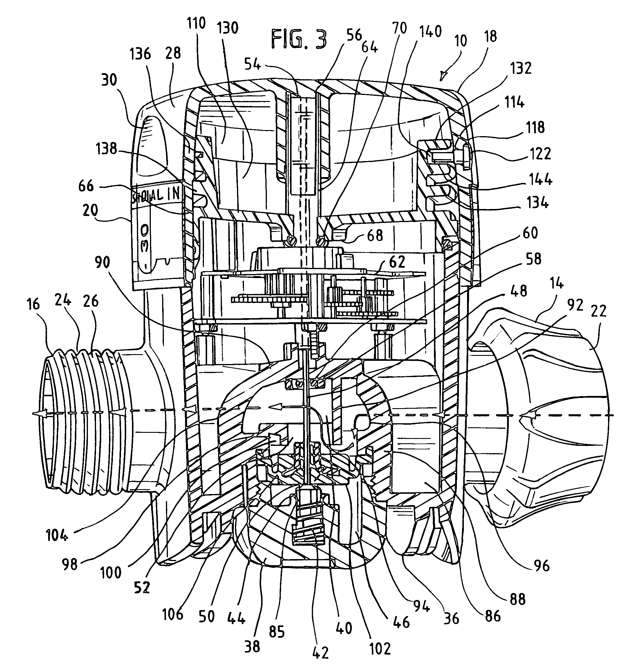
[0017]While the present invention is capable of embodiment in various forms, there is shown in the drawings and will hereinafter be described a presently preferred embodiment with the understanding that the present disclosure is to be considered as an exemplification of the invention, and is not intended to limit the invention to the specific embodiment illustrated.
[0018]FIGS. 1-2 show a mechanical timing valve 10 which is one example of the present invention. The mechanical timing valve 10 has a main body 12 which has a water inlet 14 and a water outlet 16. The main body 12 also has a dial knob 18 and a corresponding indicator collar 20. The water inlet 14 has a hose coupler 22 which is a standard sill cock connector although other types of hose connectors may be used such as a quick connect connector. The water outlet 16 has a male coupling member 24 which has a threaded exterior 26 for coupling to a hose or another watering device.
[0019]The dial knob 18 has a gripping surface 28 ...
PUM
 Abstract
Description
Claims
Application Information