Work feeding and conveying device for a planing machine

Inactive Publication Date: 2007-08-07
CHUANG BOR YANN
View PDF6 Cites 13 Cited by
  • Summary
  • Abstract
  • Description
  • Claims
  • Application Information

AI Technical Summary

Benefits of technology

[0006]The objective of this invention is to offer a work feeding and conveying device for a planing machine, which is provided with a conveying unit on the intermediate base of a planing machine. The conveying unit consists of a front shaft, a rear shaft and a conveying belt. The front shaft is secured at the front end of the intermediate base and has one end connected with a power source for driving the front shaft to rotate. The rear shaft is pivotally connected with the rear end of the intermediate base, able to be moved back and forth horizontally a p

Problems solved by technology

Thus, in the course of planing, the front and the rear end of the work cannot be kept flat and straight, and in consequence the work fails to be planed smoothly and precisely.
In addition, as shown in FIG. 2, in order to enable the motor to simultaneously drive both the planing knife 132 and the press-convey rollers 133, which are quite di

Method used


Image

  • Work feeding and conveying device for a planing machine
  • Work feeding and conveying device for a planing machine
  • Work feeding and conveying device for a planing machine

Examples


Example

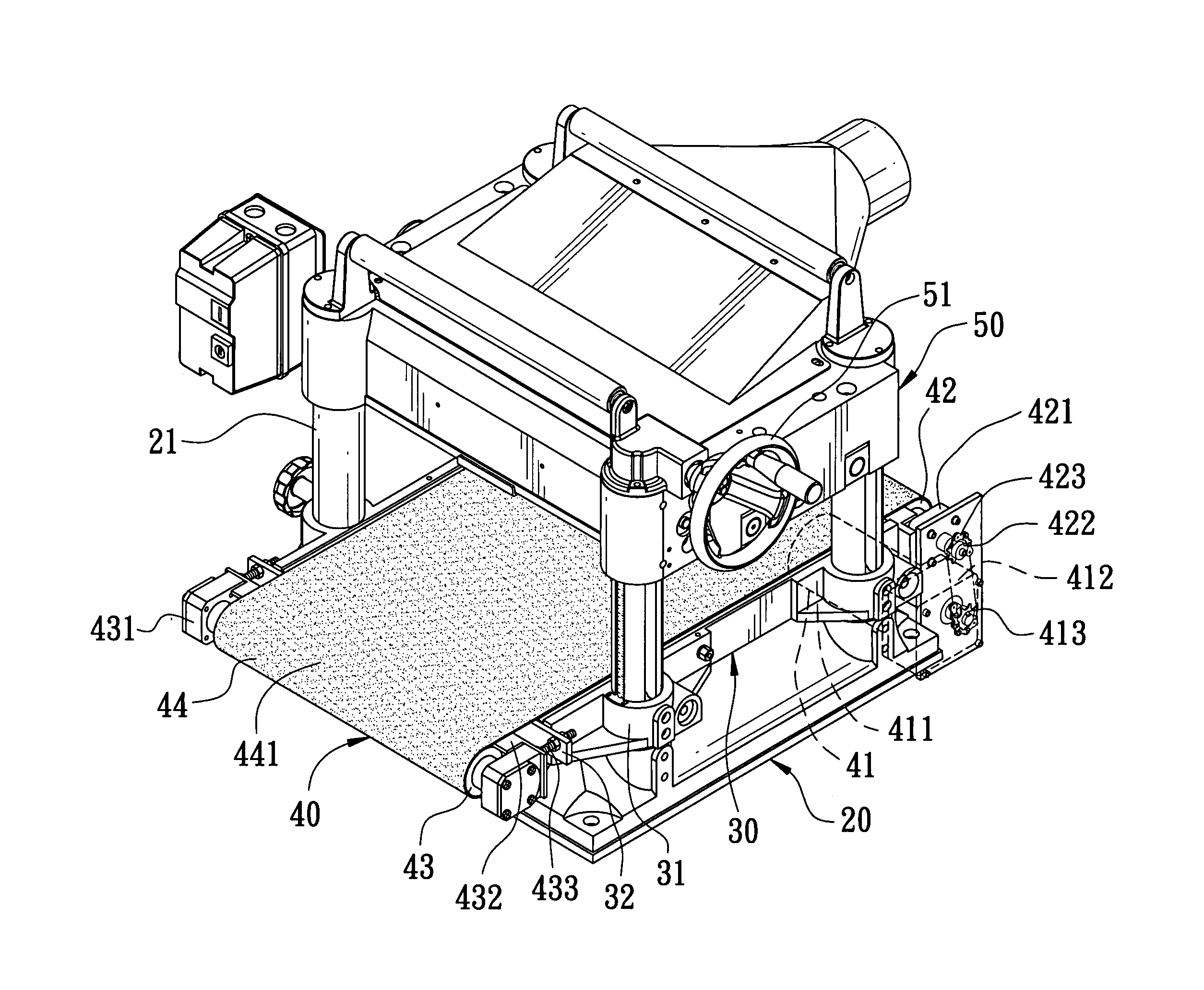
[0014]A first preferred embodiment of a work feeding and conveying device for a planing machine in the present invention, as shown in FIGS. 3, 4 and 5, includes a planing table 20, an intermediate base 30, a conveying unit 40 and an upper base 50 combined together.

[0015]The planing table 20 with a flat top has four threaded rods 21 vertically fixed on its periphery and a motor (not shown) installed in the interior.

[0016]The intermediate base 30 has it periphery provided with four vertical projections respectively bored with a threaded hole 31 to be respectively screwed on the four threaded rods 21 of the planing table 20. The intermediate base 30 further has its rear end provided with a protruding block 32 having its opposite ends respectively bored with a through hole 321 and its central portion bored with two slide holes 322. Furthermore, the intermediate base 30 has two insert holes 33 bored in the central portion of its rear wall and aligned to the two slide holes 322 of the pro...


PUM

PropertyMeasurementUnit
Forceaaaaaaaaaa
Distanceaaaaaaaaaa
Friction coefficientaaaaaaaaaa

Abstract

A work feeding and conveying device for a planing machine includes a conveying unit assembled on an intermediate base of a planing machine. The conveying unit has a power source, a front shaft, a rear shaft and a conveying belt. The front shaft is secured at the front end of the intermediate base and connected with a power source for being rotated. The rear shaft is pivotally connected with the rear end of the intermediate base, able to be moved back and forth horizontally for a present distance. The conveying belt formed with a rough surface with high friction coefficient is fitted around the intermediate base and passes on the front and the rear shaft. The conveying belt can smoothly convey a work piece, and evenly apply force on its surface, able to carry out wood processing precisely.

Description

BACKGROUND OF THE INVENTION[0001]1. Field of the Invention[0002]This invention relates to a work feeding and conveying device for a planing machine, particularly to one provided on an intermediate base with a conveying unit able to convey a work with even force to enable the work piece to be processed smoothly and precisely.[0003]2. Description of the Prior Art[0004]A conventional planing machine 10, as shown in FIG. 1, includes a flattop planing table 11 assembled thereon with an intermediate base 12 and an upper base 13. The intermediate base 12 is a flat stand pivotally disposed with two rollers 121 at its upper end, and the upper base 13 is provided thereon with a rotary arm 131 able to be turned for adjusting the distance between the intermediate base 12 and the upper base 13. Further, the upper base 13 is pivotally installed inside with a planing knife 132 driven by a motor (not shown) to carry out planing work. The planing knife 132 has its front and rear side respectively an...

Claims


Application Information

Patent Timeline
IPC IPC(8): B27C1/04B23C9/00
CPCB27C1/04B27C1/12Y10T409/30532Y10T409/305432
Inventor CHUANG, BOR-YANN
Owner CHUANG BOR YANN
Why Eureka
Try Eureka