Ophthamoscope

Inactive Publication Date: 2007-08-07
KEELER
View PDF1 Cites 1 Cited by
  • Summary
  • Abstract
  • Description
  • Claims
  • Application Information

AI Technical Summary

Benefits of technology

[0005]According to the invention, there is provided an ophthalmoscope comprising illuminating optics for projecting a beam of light into an eye under examination and a housing containing imaging optics for creating an image of said eye for viewing by a user, the imaging optics comprising an objective lens system and an eye piece lens system, wherein the ophthalmoscope includes two corneal reflex stops situated one on either side of the corneal image formed by the objective lens system in use, to block reflections from the cornea of the eye under examination.

Problems solved by technology

However, despite these stops, both types of ophthalmoscope allow some corneal glare to obscure the viewed image.

Method used


Image

  • Ophthamoscope
  • Ophthamoscope
  • Ophthamoscope

Examples


Embodiment Construction

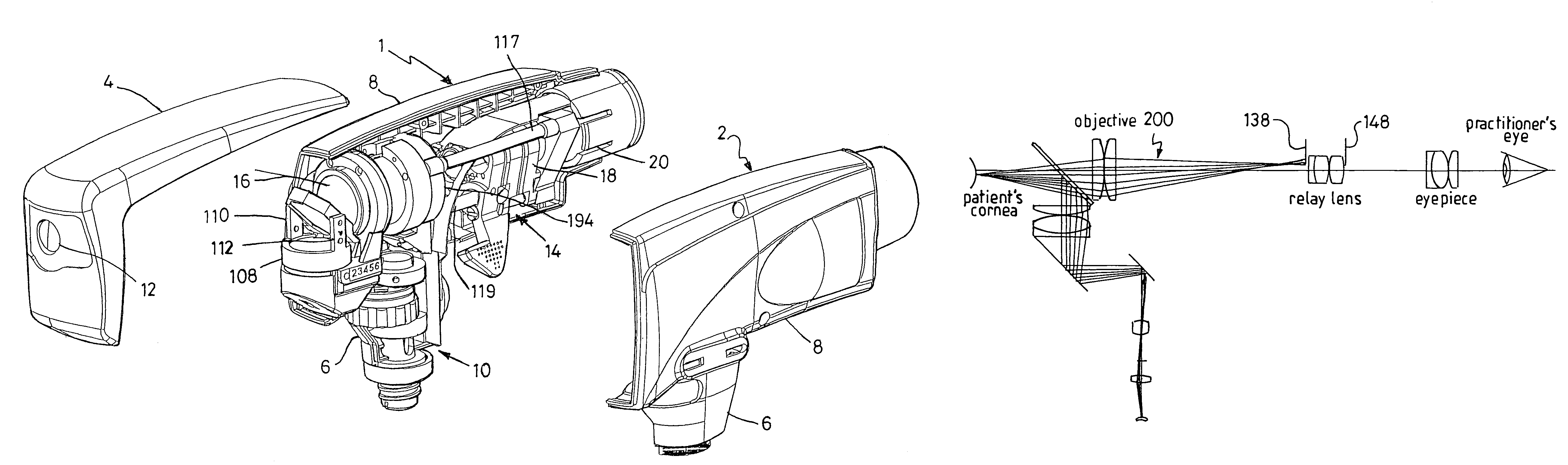
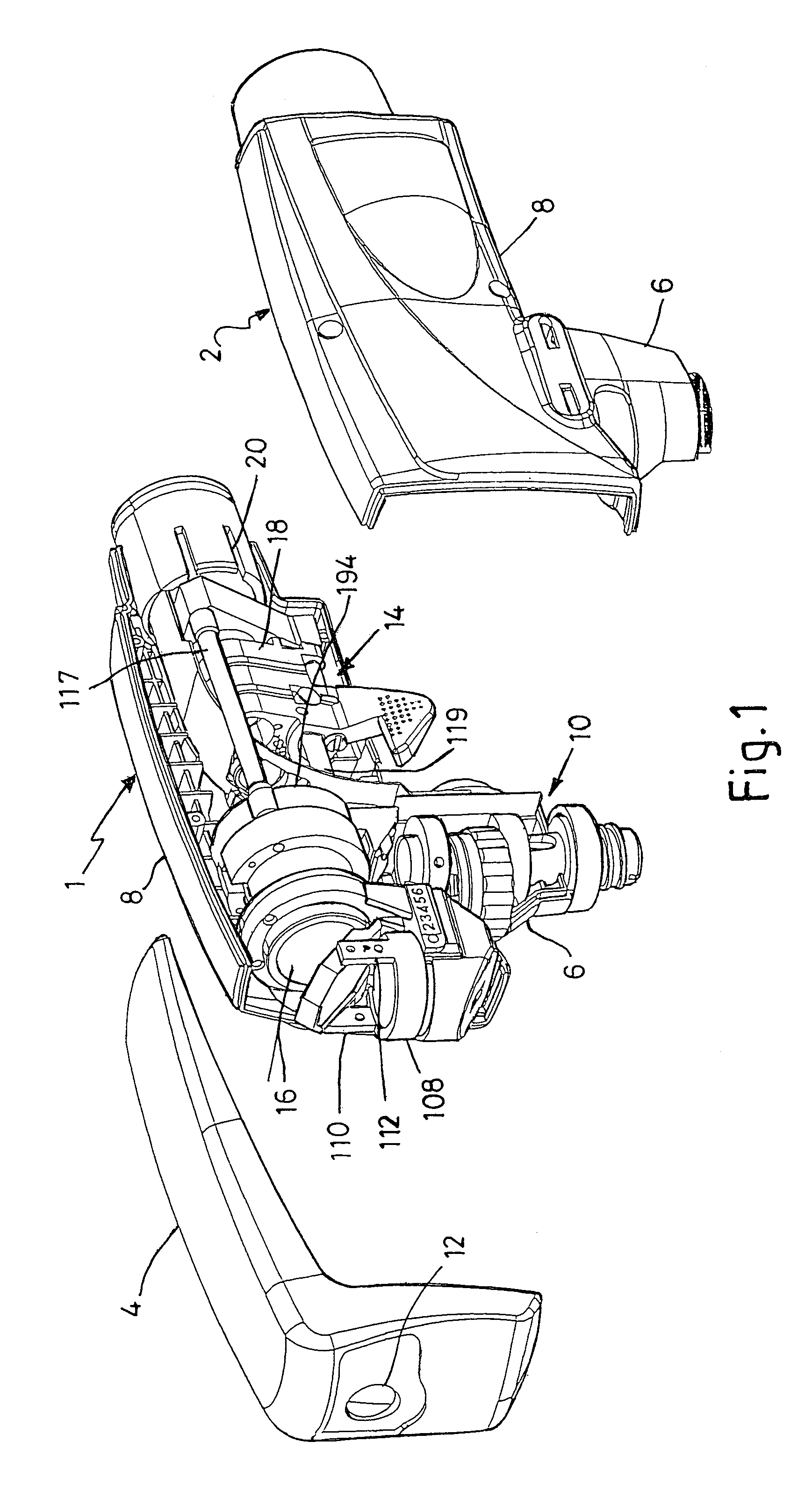
[0053]With reference to FIG. 1, an ophthalmoscope in accordance with the invention comprises a housing having two side sections 1 and 2 which are mirror images of each other and a front and top housing section 4 which extends over the tops of the housing sections 1 and 2 and down the front of the ophthalmoscope. Each side section has a handle portion 6 extending from a main body portion 8. The handle portions 6 extend vertically from the main portion 8, and contains illuminating optics 10 for projecting a beam of illuminating light through a window 12 in the front of the housing section 4. The portion of the housing section 4 defining the window 12 constitutes a front stop of the ophthalmoscope. The volume defined by the body portions of the housing sections 1 and 2 contains the ophthalmoscope's imaging optics, generally referenced 14.

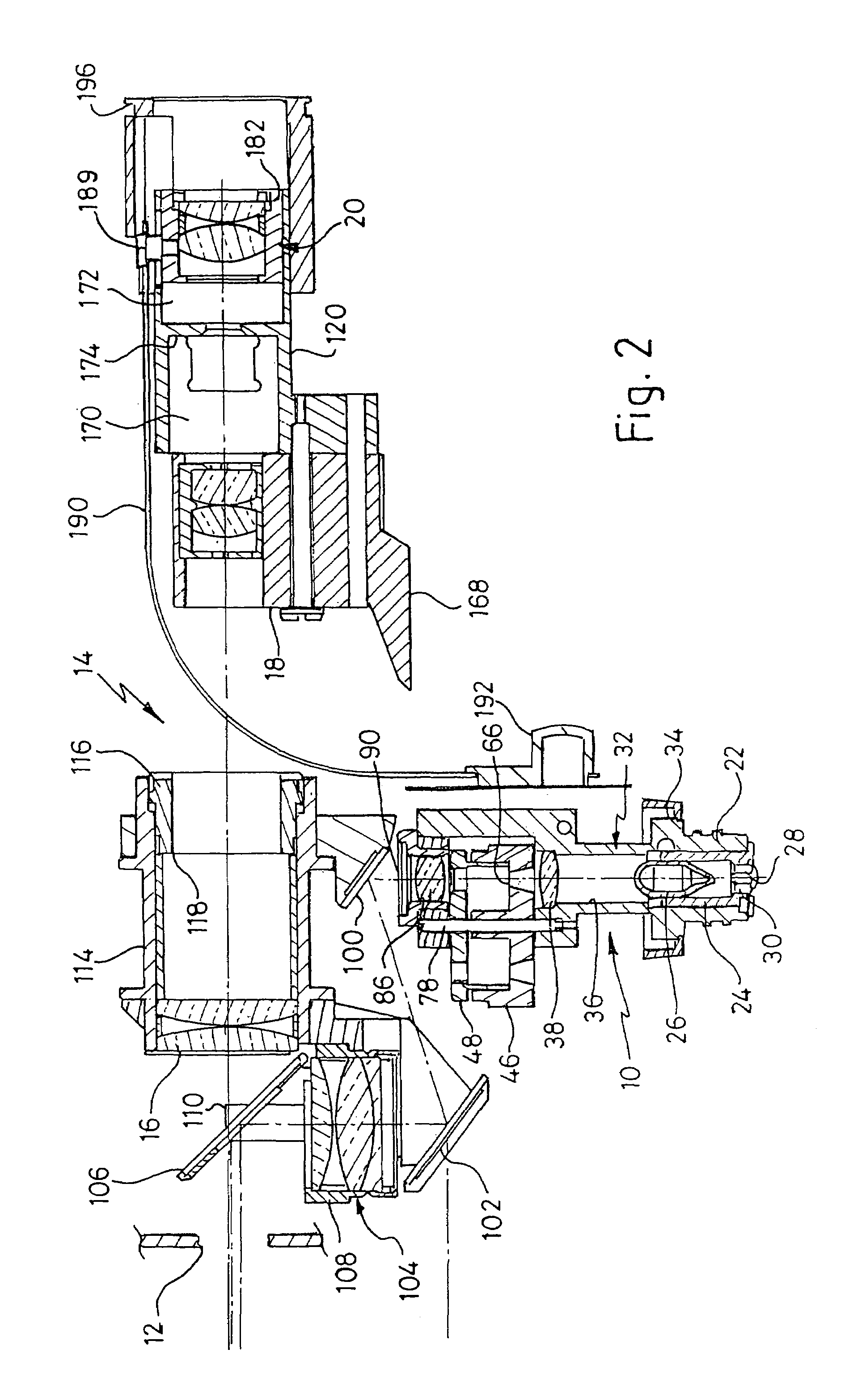
[0054]The imaging optics 14 include an objective lens system 16 from which light from an eye under examination passes through either one or two interm...


PUM


Abstract

An ophthalmoscope has illuminating optics (10) for projecting a beam of light into an eye under examination and imaging optics (14) for creating an image of said eye for viewing by a user. The imaging optics comprises an objective lens system (16) and an eye piece lens system (20). Two corneal reflex stops (138 and 148) are positioned one on either side of the corneal image formed by the objective lens system. The stops block reflections from the cornea of the eye under examination over a range of distances of the ophthalmoscope from the eye. The use of the two corneal reflex stops results in the precise positioning of the ophthalmoscope relative to the eye under examination not being critical to the blocking of the corneal reflex.

Description

FIELD OF THE INVENTION[0001]This invention relates to ophthalmoscopes.BACKGROUND TO THE INVENTION[0002]Ophthalmoscopes are instruments used to view the fundus of an eye, and generally comprise a light source and a series of optical elements for directing illuminating light from the source into an eye under examination and imaging optics through which the illuminated fundus is viewed. In an indirect ophthalmoscope, a practitioner (or other user) views a real image of the fundus rather than the fundus itself.[0003]A significant amount of the illuminating light beam is reflected from the cornea of an eye under examination, and it is important that these reflections are not seen by the practitioner / user as they will obscure the view of the fundus under examination. U.S. Pat. No. 3,586,424 shows an ophthalmoscope in which corneal reflexes are blocked by a single stop between an objective and an eye piece lens system of the ophthalmoscope. WO 00 / 30527 shows an ophthalmoscope in which illu...

Claims


Application Information

Patent Timeline
Patent Type & Authority Patents(United States)
IPC IPC(8): A61B3/14A61B3/12A61B3/15
CPCA61B3/156
Inventor BURROWS, CLIVE HARROLD THOMASCHURCH, KELVYNCHURCH, STEPHENFREEMAN, DAVID ERNEST LANEMATTHEWS, JAMES ROBERT ARNOLD
Owner KEELER
Why Eureka
Try Eureka