
Backlight button assemblage

a backlight button and button technology, applied in the field of backlight button structure, can solve the problems of difficult keyboard operation, non-uniform light, and user discomfor

Active Publication Date: 2007-08-07
AIXIN TECH
View PDF8 Cites 30 Cited by
  • Summary
  • Abstract
  • Description
  • Claims
  • Application Information

AI Technical Summary

Benefits of technology

"The present invention provides a backlight button assemblage that can achieve uniform lighting and avoid partial dazzling spots, while reducing the quantity of light-emitting elements and saving fabrication costs. The assemblage includes an opaque button, a light-guiding element, and a light-emitting element. The light emitted from the light-emitting element is transmitted through a direct or reflective path to the light-guiding element, which guides the light towards the front side of the button and transmits it out. This results in a well-controlled beam of light that is evenly distributed over the button, achieving uniform lighting and avoiding dazzling spots."

Problems solved by technology

In some places, such as conference room, interior of car or airplane, as light is dim, an operation of keyboard is difficult when a user operates electronic products, such as a computer, PDA, projector, mobile phone, etc.
However, the transparent button results in the light projecting directly into the user's eyes, which incurs the discomfort for the user.
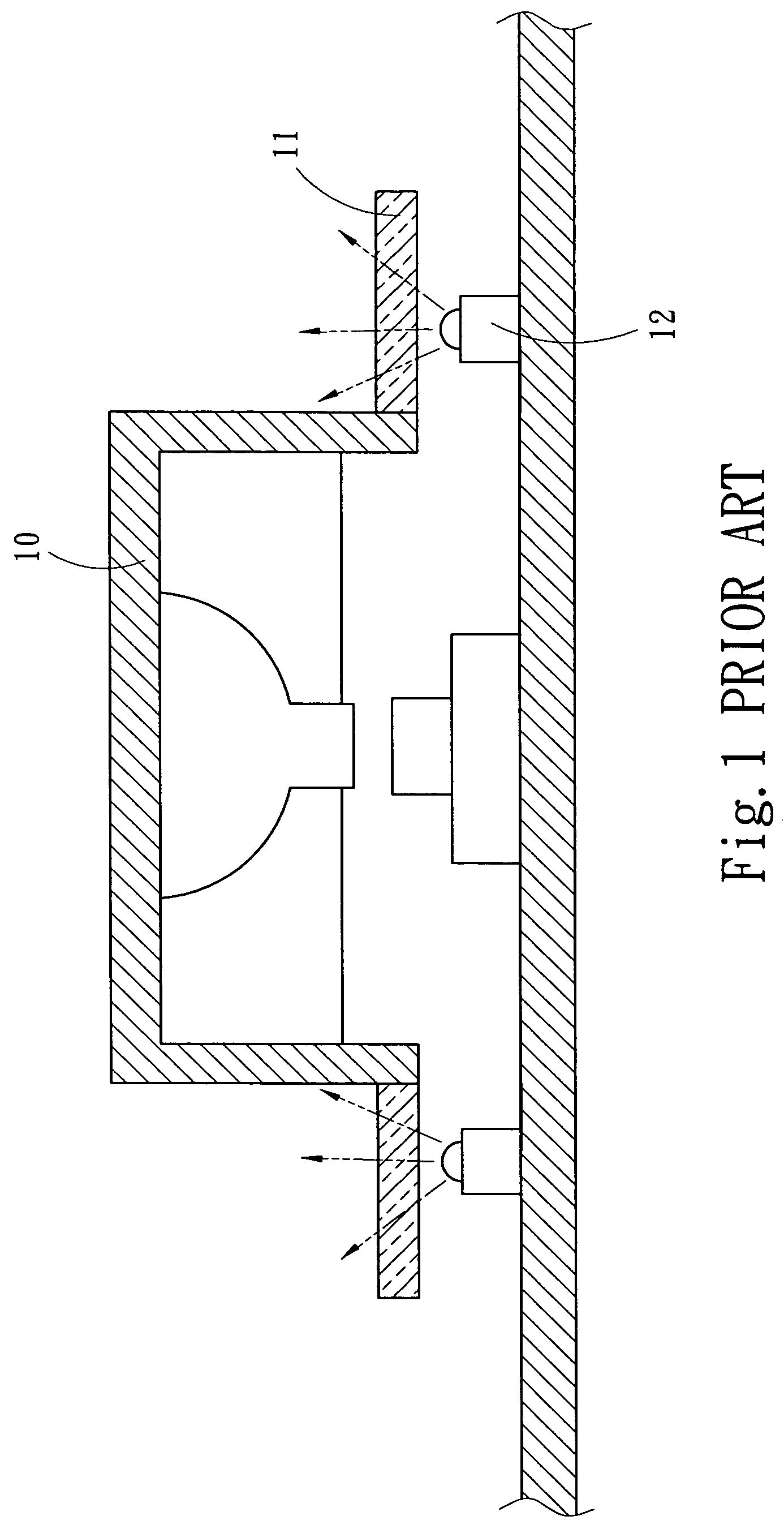
But the design of installing the light-emitting element 12 under the light-guiding element 11 still results in dazzling spots on a light-exiting surface of the light-guiding element 11 and light non-uniformity.
However, utilizing more light-emitting elements 12 results in more fabrication cost and power consumption.

Method used


Image

  • Backlight button assemblage
  • Backlight button assemblage
  • Backlight button assemblage

Examples


first embodiment

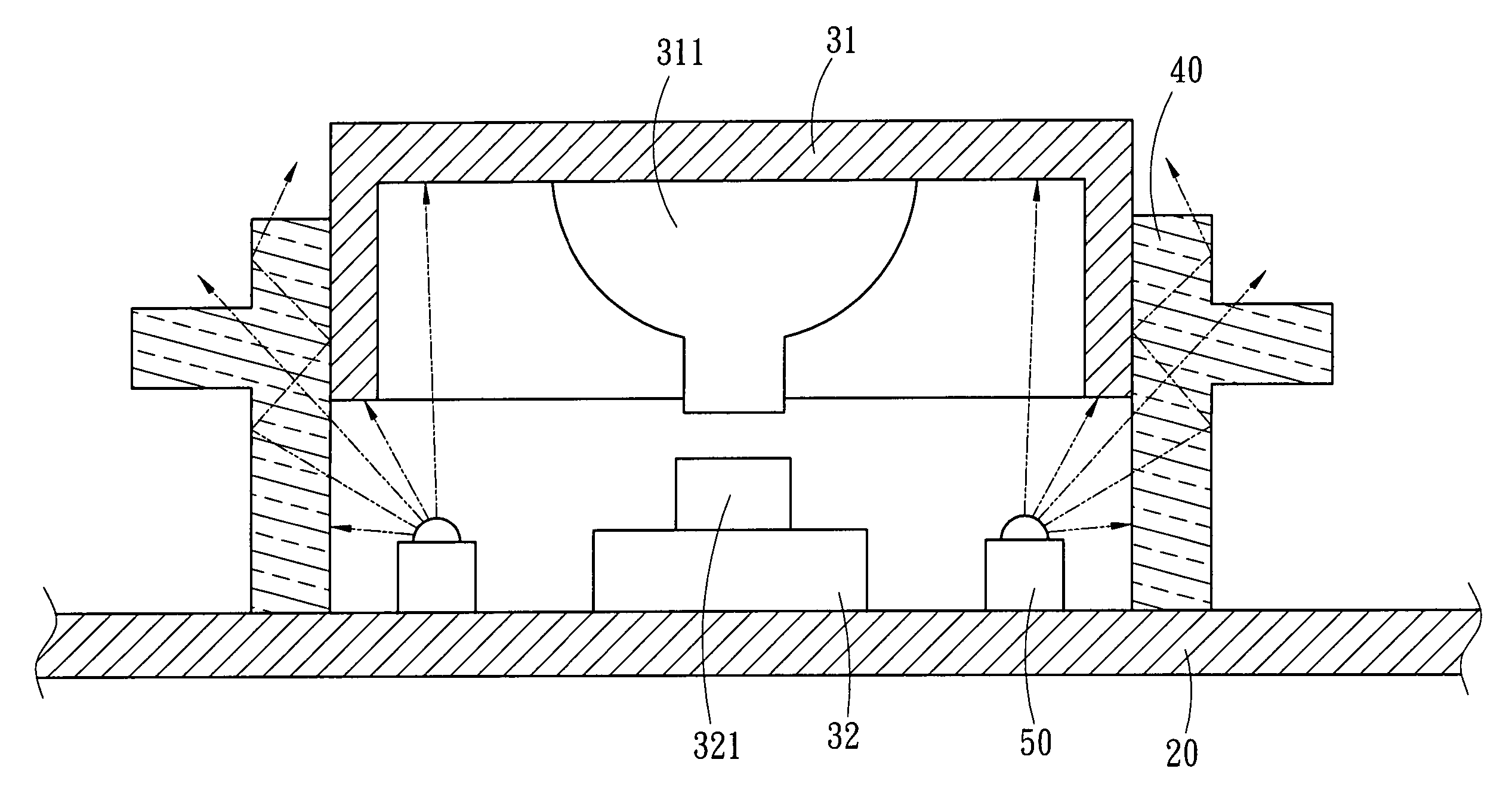
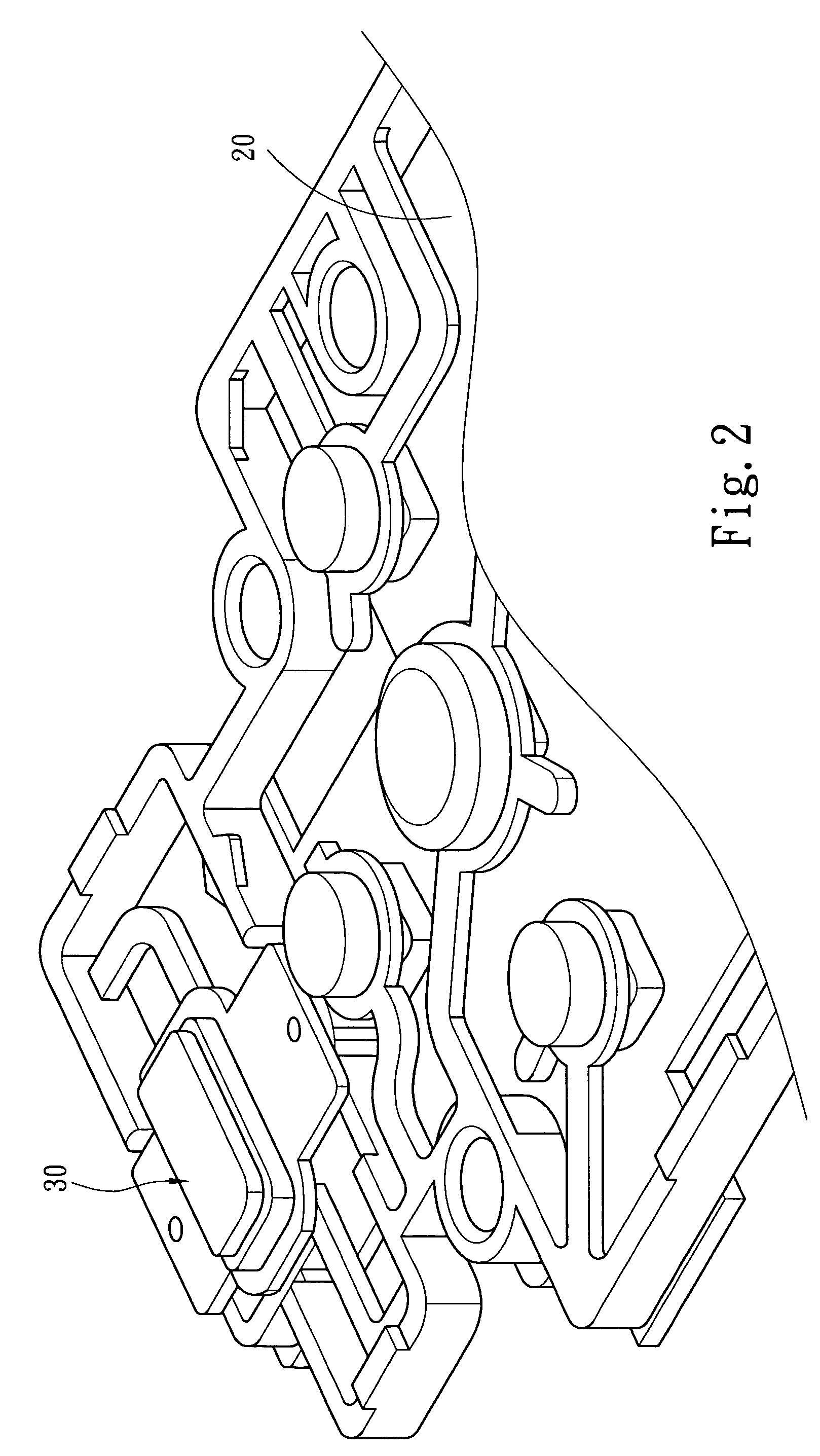
[0017]As shown in FIG. 2 and FIG. 3, according to the present invention, a backlight button assemblage 30 includes a button 31, a light-guiding element 40, and at least one light-emitting element 50.

[0018]The button 31 is opaque and disposed above a switch 32. A bottom of the button 31 usually has a protrusion 311, which is used to press a contact end 321 of the switch 32. In a normal state, the button 31 is supported by support elements, such as a spring (not shown), or directly supported by the contact end 321 of the switch 32.

[0019]The light-guiding element 40 is transparent. The shape of light-guiding element 40 matched a contour of the button 31 and is disposed along the perimeter of the button 31, The light-guiding element 40 can not interfere with a movement of the button 31. The light-guiding element 40 is annular, and is fixed to or stands on the surface of a printed circuit board (PCB) 20. The light-guiding element 40 guides a light and is made of a transparent material, s...

second embodiment

[0022]Refer to FIG. 6, which discloses the backlight button assemblage in the present invention, a directional light-emitting element 50a is adopted. In this embodiment, the objectives of the present invention are achieved via a modification of the shape of the light-guiding element and the position of the light-emitting element 50a. In this embodiment, the light-guiding element 40a is a transparent structure and has a L-shaped section, which has at least one corner 41. Two ends of the L-shaped transparent structure are a light incident surface 42 and a light-emitting surface 43 respectively. The light-emitting surface 43 surrounds the perimeter of the button 31. The light incident surface 42 is near and perpendicular to a surface of the PCB 20. The light-emitting element 50a is disposed in front of the light incident surface 42, and the light-emitting direction (indicated by the arrow B in FIG. 6) is parallel to the surface of the PCB 20. The light-emitting direction of a light emi...


PUM


Abstract

A backlight button assemblage includes an opaque button, a light-guiding element, and a light-emitting element. The light-emitting element is disposed under the button and light emitted from the light-emitting element is guided to the front side of the button via the light-guiding element surrounding the button. Light can therefore be evenly distributed over the light-guiding element, and uniformity of light achieved, so that partial dazzling spots are avoided, the quantity of light-emitting elements is reduced, and fabrication costs are saved.

Description

FIELD OF THE INVENTION[0001]The present invention relates to a structure of backlight button, particularly to a backlight button assemblage, which has an improved light-guiding structure.BACKGROUND OF THE INVENTION[0002]With the progress of science and technology, the utility and popularity of the electronic product grow obviously. In some places, such as conference room, interior of car or airplane, as light is dim, an operation of keyboard is difficult when a user operates electronic products, such as a computer, PDA, projector, mobile phone, etc.[0003]To solve the above-mentioned problem, Taiwanese Utility Model Patent Publication No. M248011 discloses a backlight button. The backlight button includes a button body and a guiding element. The button body is transparent and the guiding element is extended from at least one side of the button body. A light-emitting element is disposed in a position of a printed circuit board (PCB), which corresponds to the button body, and an inchin...

Claims


Application Information

Patent Timeline
Patent Type & Authority Patents(United States)
IPC IPC(8): H01H9/18
CPCH01H13/83H01H2219/06H01H2219/062H01H2219/0622
Inventor FU, WEN-CHICHANG, TAI-LI
Owner AIXIN TECH
Learn More