Backlight using planar hologram for flat display device

a flat display device and backlight technology, applied in static indicating devices, lighting and heating apparatuses, instruments, etc., can solve the problems of increasing manufacturing costs, complicated assembly process of backlights, and difficulty in assembling backlights, so as to reduce the degree of color separation of light, increase the output amount of light, and achieve maximum diffraction efficiency

Inactive Publication Date: 2007-08-07
SAMSUNG ELECTRO MECHANICS CO LTD
View PDF27 Cites 38 Cited by
  • Summary
  • Abstract
  • Description
  • Claims
  • Application Information

AI Technical Summary

Benefits of technology

[0034]When a white light source is used, the diffusion can reduce the degree of color separation of light caused by the difference in diffraction angle between light wavelengths.
[0035]In the present invention, a light path changing unit can increase the output amount of light by changing the path of high intensity light incident at an angle near 90°, so that the incident light is again incident upon the surface hologram at an angle guaranteeing the maximum diffraction efficiency.
[0036]Also, the planar hologram formed on the light guide plate enables light incident upon the light guide plate to be output from the light guide plate at an angle nearly perpendicular to the light guide plate. Accordingly, an efficient backlight having a simple structure having no prismatic plates can be provided.
[0037]In addition, the diffraction efficiency of a specific polarized light beam is rendered greatly higher than that of other polarized light beams by controlling the grating interval and depth of the surface hologram. Thus, the specific polarized light beam of light emitted from the light guide plate becomes excellent. Finally, the backlight according to the present invention can increase the light efficiency using polarization. As a result, a backlight using specific polarization can be manufactured.

Problems solved by technology

However, manufacturing of a prismatic or sinusoidal pattern on the light guide plate 13 requires a special and expensive equipment and a time-consuming process.
As a result, the assembling process of a backlight is complicated, and the manufacturing costs thereof increase.
This leads to complicated, expensive backlights.
This causes an increase in the manufacturing costs of backlights.

Method used


Image

  • Backlight using planar hologram for flat display device
  • Backlight using planar hologram for flat display device
  • Backlight using planar hologram for flat display device

Examples


first embodiment

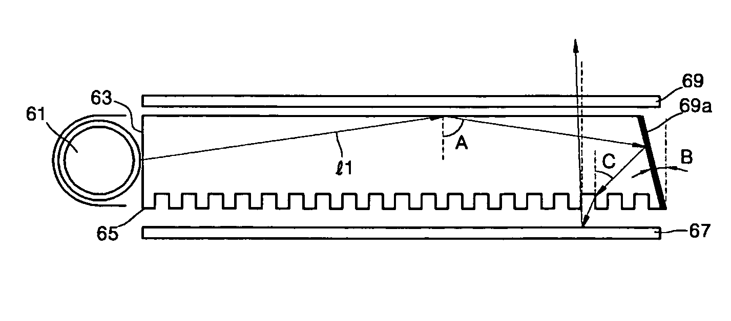
[0066]Referring to FIG. 4A, a backlight for a flat display device according to the present invention includes a light source 61, a light guide plate 63, a reflection plane 69a, a planar hologram 65 and a reflection plate 67. The light source 61 emits light l1. The light guide plate 63 directs the light l1 emitted from the light source 61 by totally reflecting the light l1. The reflection plane 69a is used as a light path changing unit for changing the path of the light l1. The planar hologram 65 diffracts light to output light at an angle of no less than 80° or at a predetermined design angle with respect to the plane of the light guide plate 63. The reflection plate 67 is positioned at the bottom surface of the planar hologram 65, reflects light diffracted by the planar hologram 65, and sends reflected light back to the light guide plate 63.

[0067]The light source 61 can be one of a laser diode (LD), a light emitting device (LED) and a cold cathode fluorescent lamp (CCFL). As descri...

fourth embodiment

[0081]FIG. 5B shows a backlight according to the present invention. Referring to FIG. 5B, the light guide plate 63 has the planar hologram 65 formed on its upper side. In order to change the incidence angle of light l4 upon the planar hologram 65, the inclination angle B of the reflection mirror 68b is set in the same way as the inclination angle B of the reflection mirror 68a for the backlight of FIG. 5A.

fifth embodiment

[0082]FIG. 6A shows a backlight according to the present invention. Referring to FIG. 6A, a diffraction grating 66a is included as a light path changing unit between the light source 61 and the light guide plate 63. The diffraction grating 66a changes the path of light l5 incident upon the plane of the light guide plate 63 at an angle close to 90°, so that the light l5 travels to be incident upon the planar hologram 65 at an angle close to the incidence angle providing the maximum diffraction efficiency. The incidence angle C with respect to the planar hologram 65 has a range as described above, and the angle for the maximum diffraction efficiency may vary within the range of the incidence angle C, depending on grating depths and grating intervals. Here, the diffraction grating 66a can be replaced by a refraction lens.


PUM


Abstract

The backlight for a flat display device including a light source, a light guide plate and a surface hologram is provided. The light guide plate is installed at one side of the light source, and light from the light source travels in the light guide plate while being totally reflected. The surface hologram is formed on at least one surface of the light guide plate. The surface hologram has a pattern of a predetermined grating interval and a predetermined grating depth in order to diffract light at a predetermined angle toward the light guide plate.

Description

BACKGROUND OF THE INVENTION[0001]This application claims the priorities of Korean Patent Application Nos. 2001-38807 and 2002-23114, filed on Jun. 30, 2001 and Apr. 26, 2002, respectively, in the Korean Intellectual Property Office, the disclosures of which are incorporated herein in their entireties by reference.FIELD OF THE INVENTION[0002]The present invention relates to the field of backlights for flat display devices, and more particularly, to a backlight for a flat display device including a light path changing unit, which makes already incident light again incident upon a planar hologram at an angle providing the maximum diffraction efficiency, and a light guide plate including the planar hologram.DESCRIPTION OF THE RELATED ART[0003]Referring to FIG. 1, a conventional backlight includes a light source 11, a light guide plate 13, a diffusion plate 19 and prismatic plates 21a and 21b. The light guide plate 13 directs light emitted from the light source 11, the diffusion plate 19...

Claims


Application Information

Patent Timeline
Patent Type & Authority Patents(United States)
IPC IPC(8): G09G3/36F21V8/00G02B6/00
CPCG02B6/0036G02B6/0055
Inventor LEE, MOON-GYUCHOI, HWAN-YOUNGCHOI, JIN-SEUNGMIN, JEE-HONG
Owner SAMSUNG ELECTRO MECHANICS CO LTD
Why Eureka
Try Eureka