Hearing aid with a microphone in the battery compartment lid

a battery compartment and microphone technology, applied in the field of hearing aids with microphones in the battery compartment lid, can solve problems such as occupying space, and achieve the effects of improving signal to noise ratio, enhancing the signal from the microphone, and reducing the noise of the battery compartmen

Inactive Publication Date: 2007-08-07
OTICON
View PDF10 Cites 21 Cited by
  • Summary
  • Abstract
  • Description
  • Claims
  • Application Information

AI Technical Summary

Benefits of technology

[0006]In an embodiment of the invention the transducer is a MEMS microphone. These microphones are easily embedded in the material of the casing part due to their small size and due to the fact that they also can withstand the temperatures and pressures used during manufacture of the casing part. Preferably injection moulding is used for the production of the casing part. This allows both hard and soft materials to be used. Also it becomes possible to use variable materials in different parts of the shell part. A soft material can be used in the immediate surroundings of the microphone, and a harder material could be used for the rest of the shell part. This will help the transducer to withstand mechanical shocks from handling.
[0009]In an embodiment two transducers are arranged in the battery lid. Hereby directionality may be obtained, or the two microphones may be used in parallel to enhance the signal from the microphones. Especially for MEMS type microphones the signal to noise ration may be low due to the small size of the active membrane, and this makes the use of more than one microphone in parallel advantageous as this may provide better signal to noise ratio.
[0010]In one embodiment of the invention the transducer or the transducers are arranged on a first side of a flexprint having electric leads which provides a signal path from the transducers to the amplifier. This is advantageous in that the flexprint can be prepared with a wide number of components before mounting in the hearing aid battery lid. Separate manual handling of the small microphone is thus avoided as these may be picked and placed on the flexprint along with other electrical components before re-flow or other fastening technique producing electric connections.
[0012]In another embodiment the battery lid has a recess in the second side thereof facing the interior of the casing, and the flexprint and the at least one transducer is retained in said recess by the use of a retaining element. The retainer element is a loose part, and it can be disassembled to allow access to the flexprint and microphones. In this way it becomes possible to make repairs or to replace malfunctioning microphones.
[0013]Another solution is to retain the flexprint and the at least one transducer against the second side of the battery lid by the use of glue or similar material. In this way the retainer element may be omitted, but on the other hand it becomes less easy to replace malfunctioning parts.
[0014]In a preferred embodiment the flexprint with the at least one transducer extends in an arch following the curvature of the battery exterior, and is electrically connected to the amplifier inside the casing. In this way the microphones and the amplifier may be placed at one and the same flexprint which is held in place at the battery lid. This is a very neat solution with a minimum of loss wiring inside the casing. Also if the battery lid has a part extending along the curvature of the battery towards the inside of the casing and if the flexprint is caused to follow the outside of this part, it is possible to provide programming connection pins directly on the outside surface of this flexprint portion.

Problems solved by technology

In prior art hearing aids the battery lid and the microphone entrance are placed side by side, and therefore both take up space.

Method used


Image

  • Hearing aid with a microphone in the battery compartment lid
  • Hearing aid with a microphone in the battery compartment lid
  • Hearing aid with a microphone in the battery compartment lid

Examples


Embodiment Construction

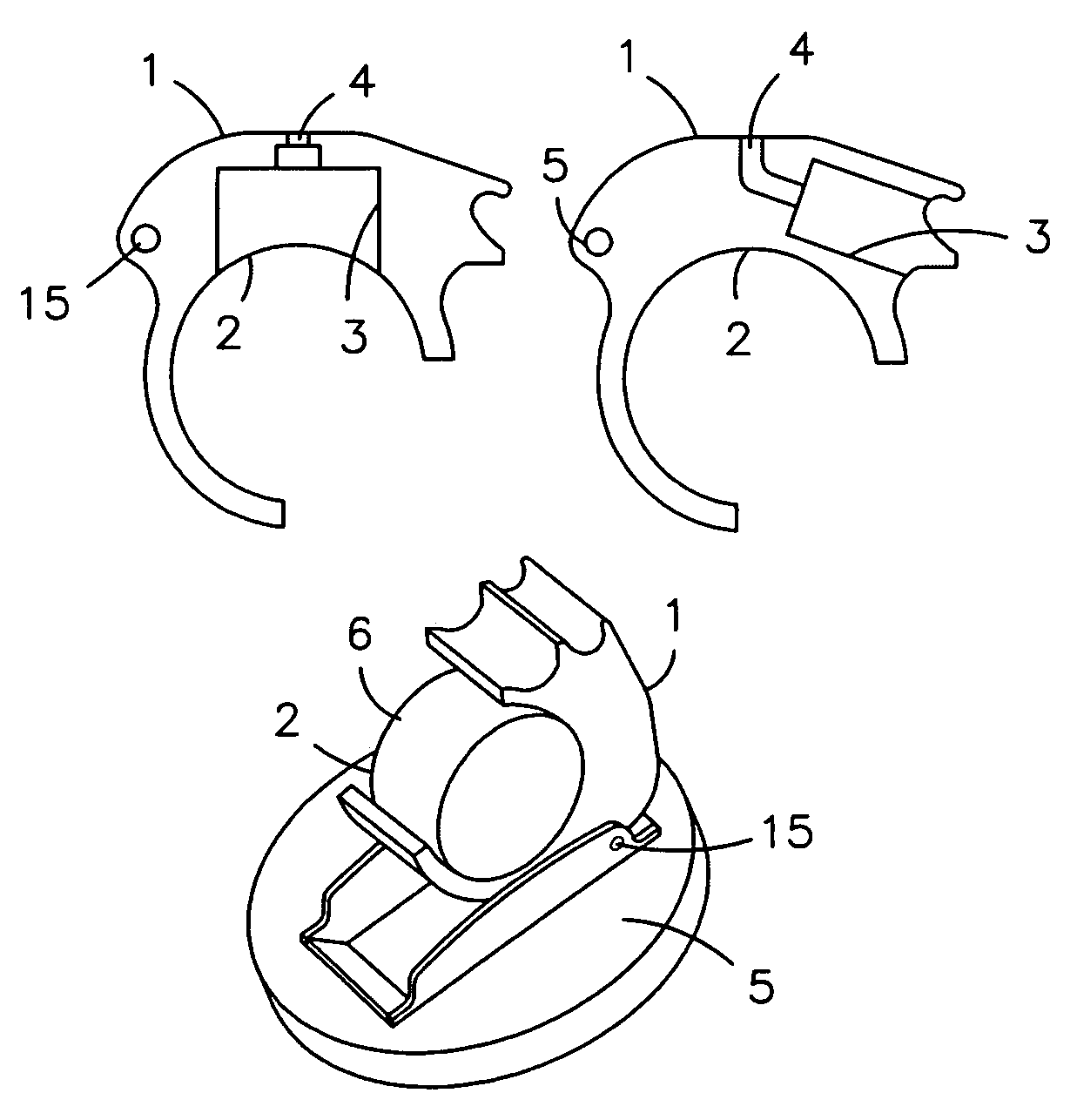
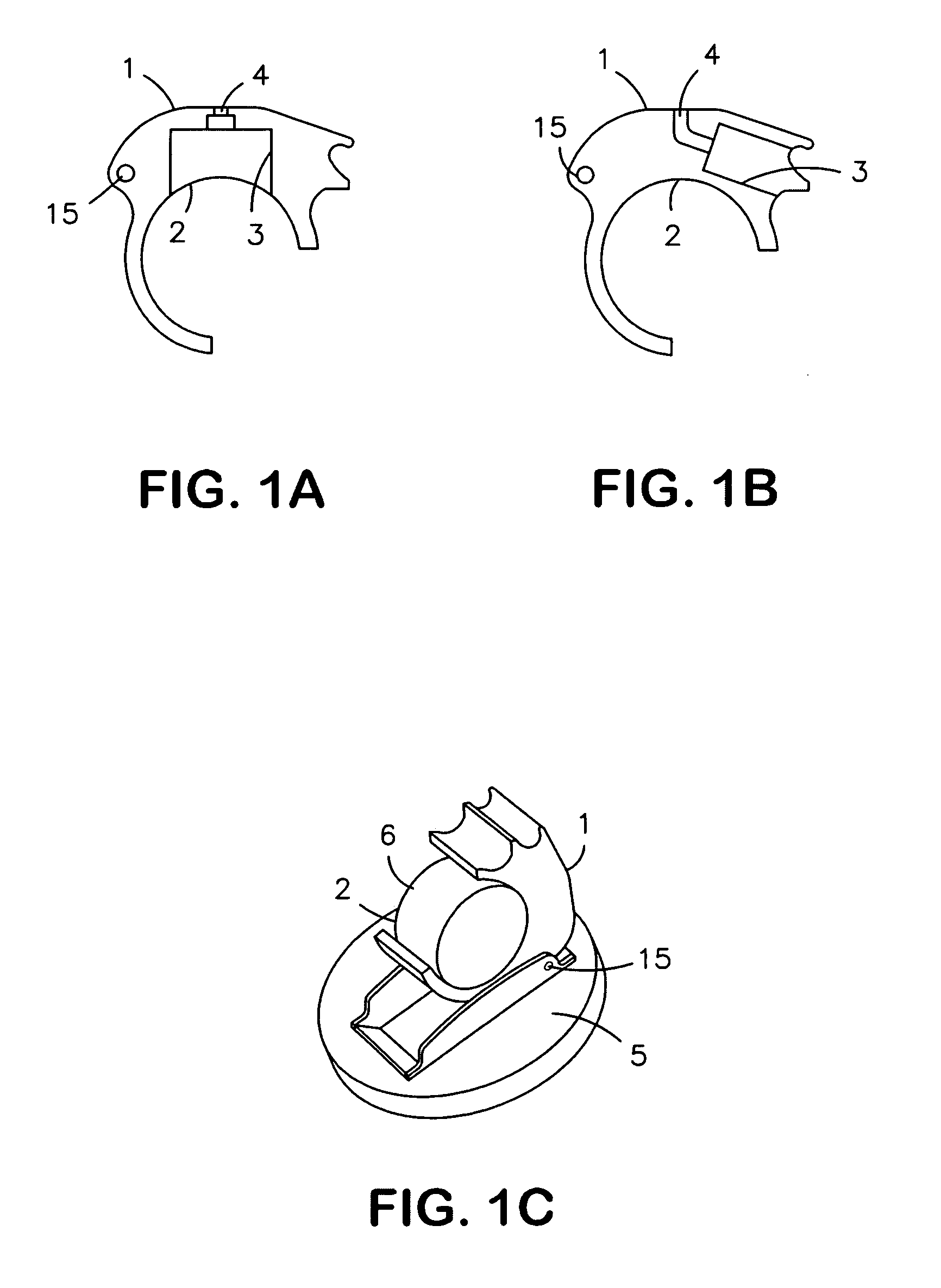
[0028]The battery lid shown in FIGS. 1A and 1B has a first side 1, which is facing the exterior and a second side 2 which faces the interior of the casing (not shown). The second side 2 is usually shaped to snugly fit the curvature of the battery. This can be seen in FIG. 1C, where the battery 6 is shown. In the embodiment of FIGS. 1A and 1B a recess 3 is shaped between the two surfaces 1 and 2. In the embodiment of FIG. 1A the recess is open toward the interior surface 2 and according to the embodiment of FIG. 1B the recess is sideways open and in both cases a microphone is insertable in the recess 3. From the bottom of the recess 3 a canal 4 is formed, which allows sound from the outside to enter the microphone port.

[0029]In FIG. 1C the battery 6 and battery lid is shown in perspective view along with a faceplate part 5. In the figure the lid is shown in the open position, and the material between the first surface 1 facing the surroundings and the second surface 2 facing the inte...


PUM

PropertyMeasurementUnit
curvatureaaaaaaaaaa
sizeaaaaaaaaaa
temperaturesaaaaaaaaaa

Abstract

A hearing aid which has a casing accommodating one or more second to electric signal converting transducers (11,12) and a signal path from the transducer (11,12) to a receiver which provides a sound signal at the ear of the user. The signal processing is provided in the signal path to ensure a signal amplification / attenuation according to the needs of the user. A battery (6) is accommodated in the casing and a battery lid is arranged with a first side (1) facing the surrounding and a second side (2) facing the interior of the casing whereby the battery lid is operable for replacement of the battery. The battery lid has a recess (3) for receiving at least one sound to electric signal converting transducer (11,12) and a sound transmission path is provided between the first side (1) of the battery lid and the at least one transducer (11, 12).

Description

AREA OF THE INVENTION[0001]The invention concerns a method of producing a hearing aid comprising a casing and at least one transducer and a signal path from the transducer to a receiver which provides a sound signal at the ear of the user, wherein signal processing is provided in the signal path to ensure a signal amplification / attenuation according to the needs of the user.[0002]The invention further concerns a hearing aid comprising a casing accommodating one or more sound to electric signal converting transducers and a signal path from the transducer to a receiver which provides a sound signal at the ear of the user, wherein signal processing is provided in the signal path to ensure a signal amplification according to the needs of the user, wherein a battery is accommodated in the casing and is replaceable through a battery lid in the casing.BACKGROUND OF THE INVENTION[0003]In the ear (ITE) hearing aids should be as small as possible and inserted as deeply as possible into the ea...

Claims


Application Information

Patent Timeline
Patent Type & Authority Patents(United States)
IPC IPC(8): H04R25/00
CPCH04R25/604B29C45/14836B29C45/14639H04R25/602H04R25/405B29C2045/14844
Inventor KRAGELUND, LASSESKINDHOJ, JORGENPETERSEN, ANDERS ERIK
Owner OTICON
Why Eureka
Try Eureka