
Method to maintain stability in a bi-directional amplifier

a bi-directional amplifier and stability technology, applied in the direction of gain control, transmission monitoring, electrical transducers, etc., can solve the problems of amplifier oscillation, severe degradation of communication system, undesired signals, etc., and achieve the effect of maintaining stability, no cost to the product, and low cos

Active Publication Date: 2007-08-07
CELLULAR SPECIALTIES
View PDF9 Cites 0 Cited by
  • Summary
  • Abstract
  • Description
  • Claims
  • Application Information

AI Technical Summary

Benefits of technology

[0012]The present invention features a low cost method of maintaining stability in a bi-directional amplifier. In one aspect of the present invention, this is performed entirely by software and adds no cost to the product. This feature is particularly relevant to the low end or low cost market to address concerns from wireless carriers that amplifiers installed with inadequate antenna isolation can oscillate in their licensed frequency range and potentially degrade their network.
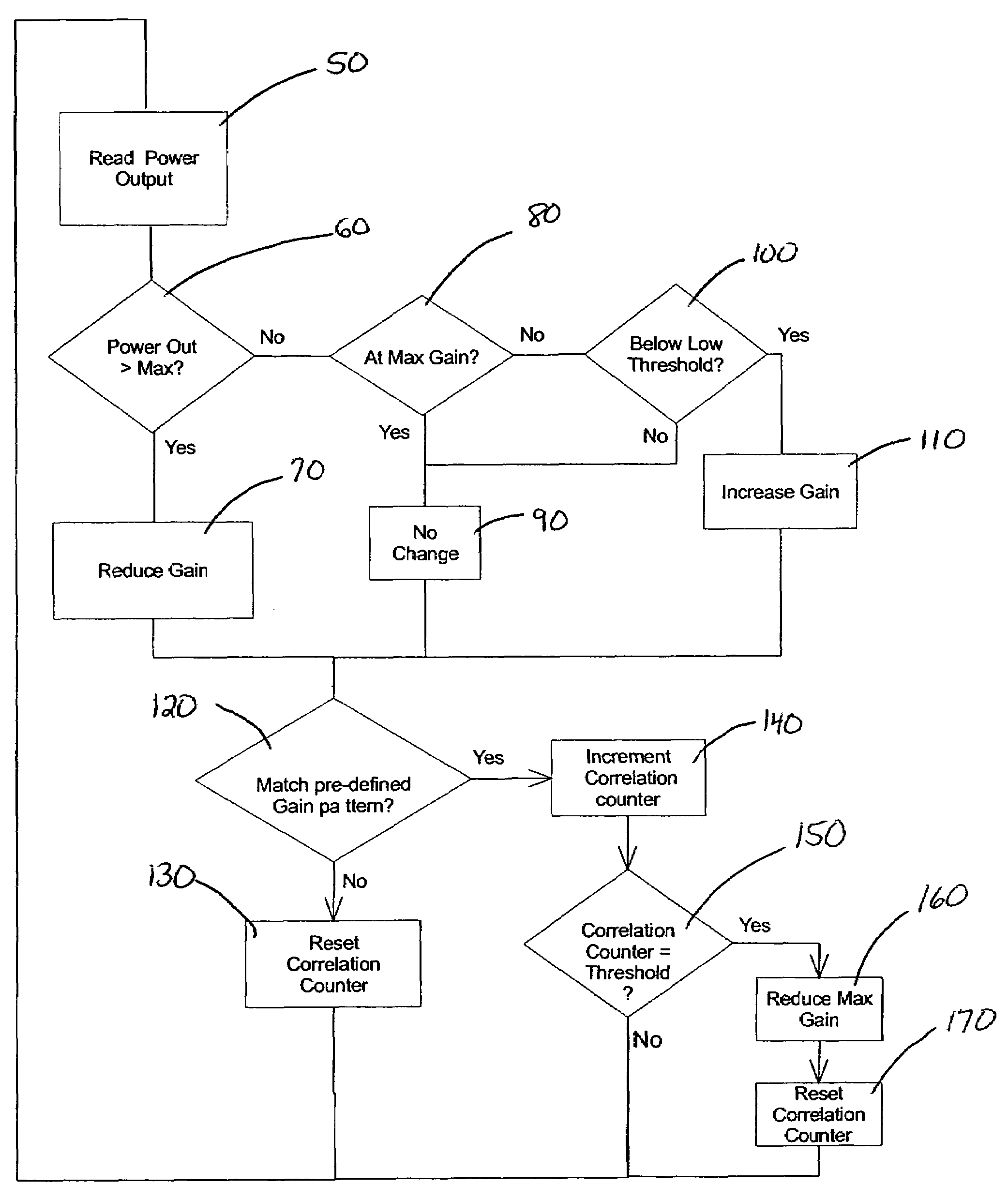
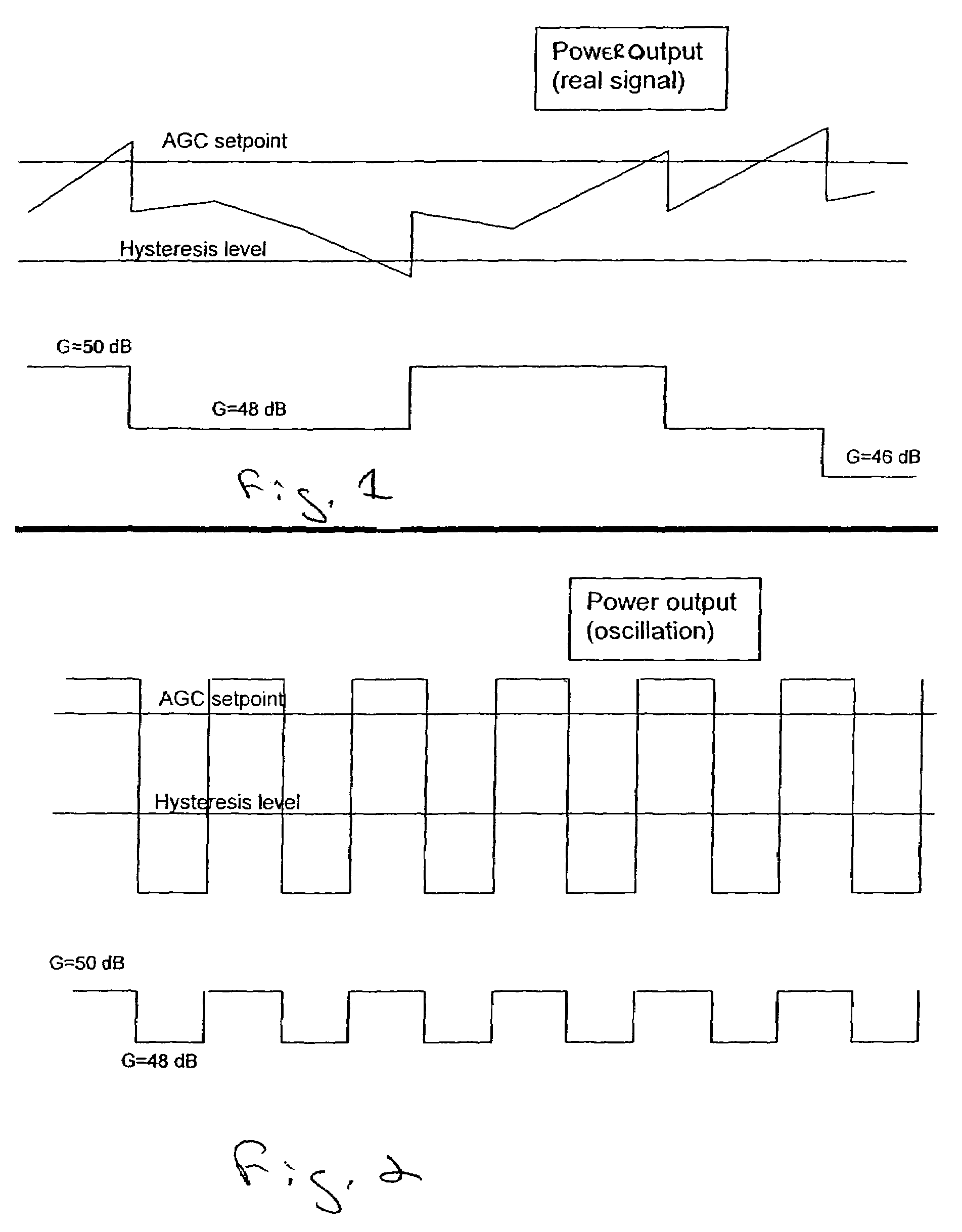
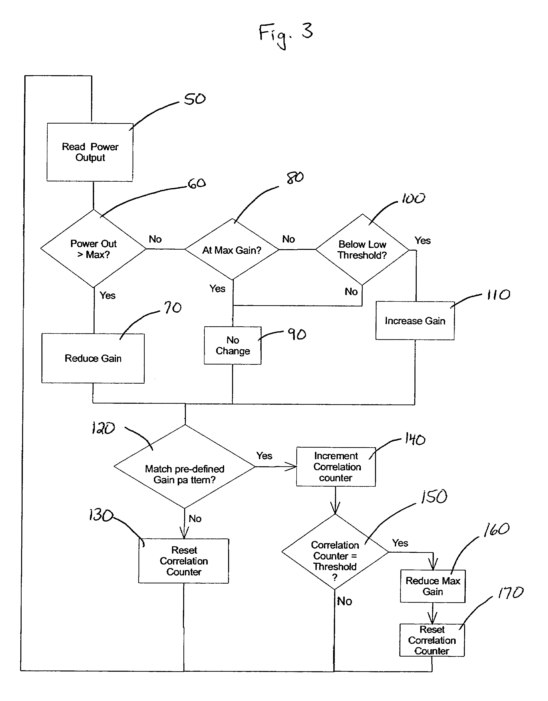
[0013]In another aspect of the invention, there is disclosed a method for detecting and controlling oscillation caused by inadequate isolation between antennas used with a bi-directional amplifier. The method includes the acts of enhancing an Automatic Gain Control (AGC) function for distinguishing between a strong signal caused by oscillation and a strong signal that actually appears in a passband of the amplifier. The response of the AGC function is characterized for each type of signal, and a correlation process is used to identify oscillation and initiate a responsive amplifier gain change to eliminate this undesirable condition. The method imposes no unique characteristics on, and causes no degradation to, the output signal.

Problems solved by technology

A finite amount of signal will be “fed back” to the first antenna to complete this feedback loop, and may cause the amplifier to oscillate, generating undesired signals in one or both passbands.
The oscillation condition may not be apparent to the user or installer; however, it may result in severe degradation of the communication system.
In some cases, it can cause an RF channel to be taken out of service completely due to interference.
However, this may cause interference and require additional circuitry to generate and detect this signal.
Attempts have been made in the prior art at power sensing at the input with a separate amplifier / detector, and imposing a “signature” on the signals, causing some degree of distortion.
Other devices rely on the timing of a specific air interface technology (GSM) to detect instability; however, it also completely switches off the RF path in the process.
Although it can detect levels of isolation above that required for oscillation in the presence of very strong signals, it requires costly dedicated circuitry and adds some degree of distortion to the outputs of the amplifier.
Low-end products have limited their functionality to detecting an overload condition (e.g., power output above a preset threshold) and shutting the amplifier off for some period of time.
This results in the amplifier being non-functional, thus failing to provide service in its coverage area.
Further, it results in high-level oscillation occurring each time the amplifier attempts to recover, potentially degrading the operation of subscriber or infrastructure equipment.

Method used


Image

  • Method to maintain stability in a bi-directional amplifier
  • Method to maintain stability in a bi-directional amplifier
  • Method to maintain stability in a bi-directional amplifier

Examples


Embodiment Construction

[0021]The present invention features a method for detecting and controlling oscillation caused by inadequate isolation between antennas used with a bi-directional amplifier. The method features an Automatic Gain Control (AGC) function for distinguishing between a strong signal caused by oscillation and a strong signal that appears in a passband of the amplifier. The enhanced Automatic Gain Control (AGC) function or feature may be incorporated into various designs. Although the present invention will be described in terms of a software algorithm, this is not a limitation of the present invention as it can also be accomplished in hardware, firmware or combinations of two or more of hardware, software and firmware.

[0022]The method features the acts of controlling the amplifier's gain (digital or analog attenuation) and accurately measuring output power of the amplifier. The act of controlling the amplifier's gain may be performed by a variable gain amplifier.

[0023]The present invention...


PUM


Abstract

A method for controlling an adjustable gain in an amplifier having an output power level and an adjustable gain is disclosed. The method includes an enhancement to a conventional Automatic Gain Control (AGC) function that distinguishes between a signal caused by oscillation and a signal that actually appears in the amplifier's passband. The method also controls unwanted and out of control amplifier oscillation using an iterative correlation process. The method prevents gain “hunting” if the output signal level is near the “set point” of the maximum permitted output level by implementing some degree of Hysteresis. The correlation process is performed by tracking a specified number of alternating gain increase / decrease cycles. If in any cycle the gain is not changed, or is changed in the same direction as in the previous cycle, the correlator is reset and the process begins again. The value and / or length of the correlator is set to minimize false detection due to random signal inputs, while maintaining acceptable sensitivity to oscillation.

Description

CROSS-REFERENCE TO RELATED APPLICATION[0001]This application claims priority from U.S. Provisional Patent Application No. 60 / 488,840, entitled “A Method to Maintain Stability in a Bi-directional Amplifier,” which was filed on Jul. 21, 2003.TECHNICAL FIELD OF THE INVENTION[0002]This invention relates to a method for detecting and controlling oscillation caused by inadequate isolation between antennas used with a bi-directional amplifier and more particularly, to a method for enhancing an Automatic Gain Control (AGC) function that distinguishes between a strong signal caused by oscillation and a strong signal that appears in a passband of the amplifier.DESCRIPTION OF THE RELATED ART[0003]Typically, an amplifier will oscillate when a sufficient component of its output is fed back to its input in phase. Generally, a situation in which the gain of the amplifier is greater than the loss between the antenna connections will bring about this condition. This situation is considered in the de...

Claims


Application Information

Patent Timeline
Patent Type & Authority Patents(United States)
IPC IPC(8): H04B17/00H04B1/04H03G3/00H03G3/30
CPCH03G3/3036
Inventor MILLS, DONALD C.
Owner CELLULAR SPECIALTIES
Learn More