Hinge coupling

a technology of coupling and hinges, applied in the field of hinge couplings, can solve the problems of compromising the purpose of storage space, disadvantages of prior art, and inability to parallel fold sections, and achieve the effect of saving storage spa

Inactive Publication Date: 2007-08-14
YOU CHING CHUAN
View PDF10 Cites 19 Cited by
  • Summary
  • Abstract
  • Description
  • Claims
  • Application Information

AI Technical Summary

Benefits of technology

[0006]It is an object of the present invention to provide a hinge coupling comprising a first connective section comprising a first hollow cylinder at one end with a first piece fastened therein, two parallel projections extending from one end of the first hollow cylinder, each projection having a bent end, a channel defined by the projections, an upper opening and a lower opening at an inner end of the channel, a bore interconnecting the upper opening and the lower opening, and a bar interconnecting the bent ends, and a second connective section comprising a second hollow cylinder, an extension projecting from one end of the second hollow cylinder, an intermediate recess for interrupting the second hollow cylinder, and a groove formed on a bottom of the recess, wherein the bar is fastened in the groove by snapping through the recess, a second piece is inserted into the second hollow cylinder by passing over the bar, and the extension is inserted into the bore by counterclockwise pivoting about the bar and locking in the bore, whereby removing the extension from the bore by pressing the second connective section until the extension releasing from the bore, and clockwise pivoting the second connective section about the bar to a limit will dispose the second connective section to be parallel with the first connective section with a distance therebetween being minimum. By incorporating this hinge coupling in, for example, a rib of an umbrella, the storage space thereof can be saved significantly.

Problems solved by technology

However, the prior art is disadvantageous since (i) the rivet fastening is a time consuming and low yield process and (ii) a parallel folding of the sections is not possible.
This in turn compromises the purpose of saving storage space.
However, the above (ii) drawback is still not addressed.

Method used


Image

  • Hinge coupling
  • Hinge coupling
  • Hinge coupling

Examples


Embodiment Construction

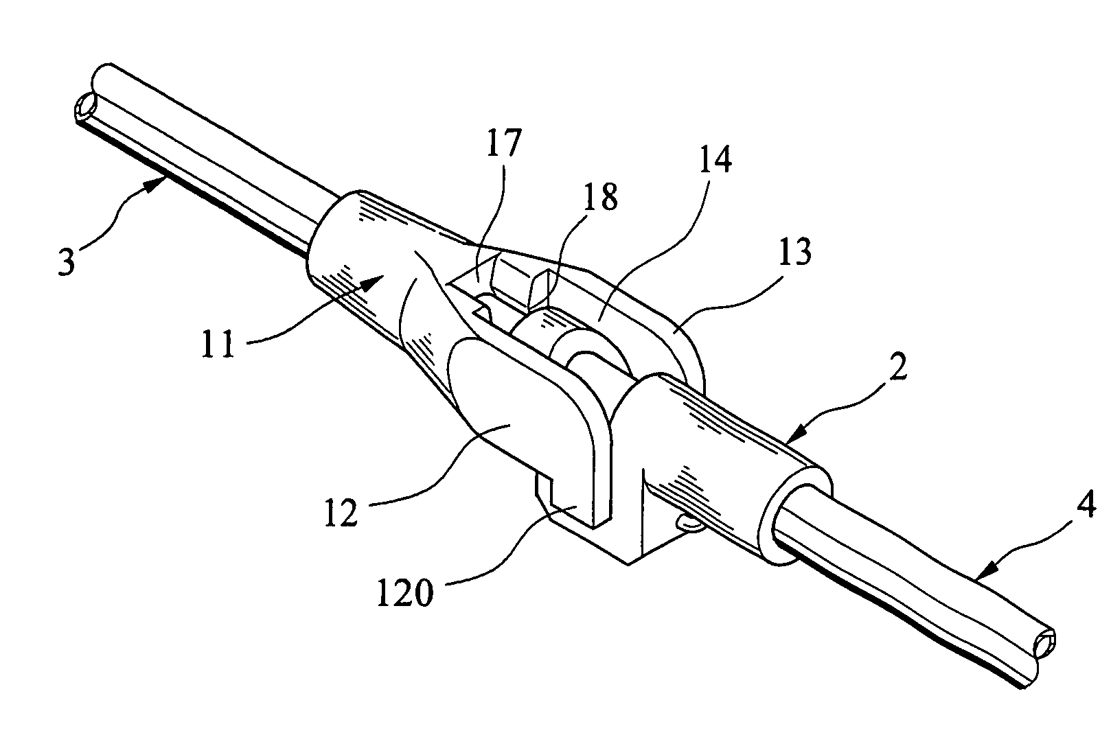
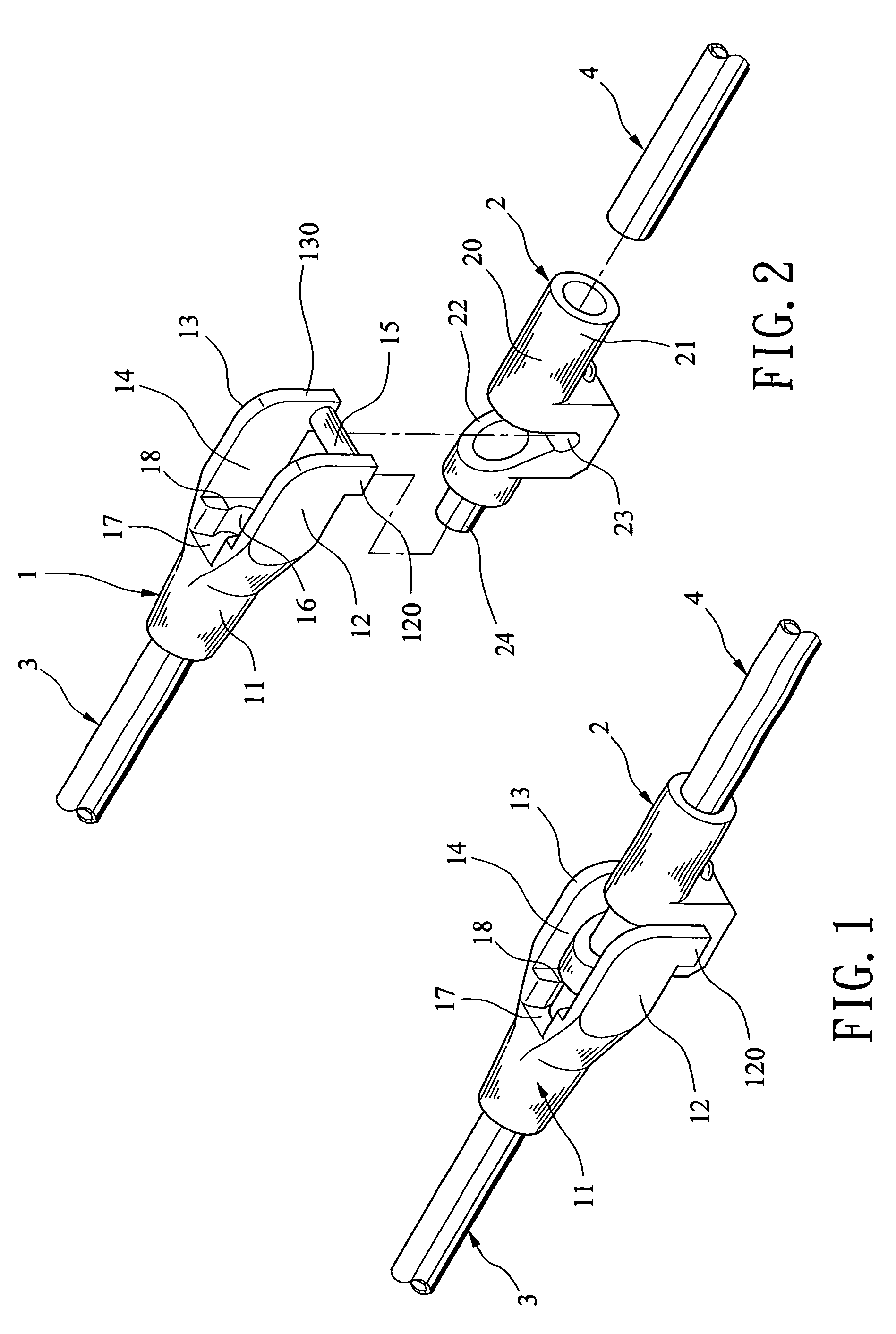
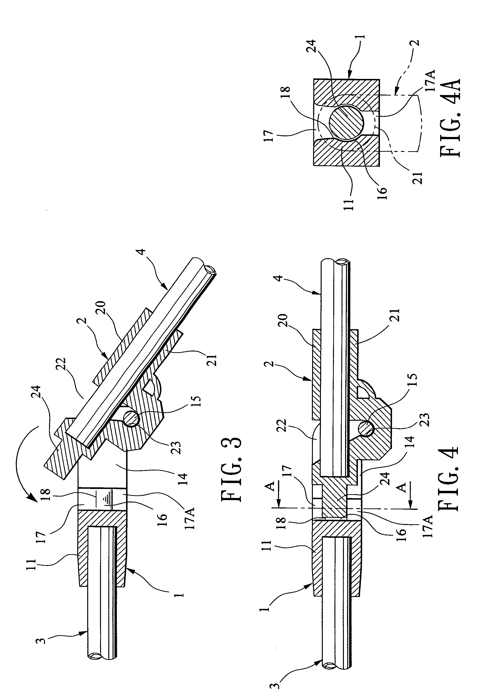
[0014]Referring to FIGS. 1 to 4A, there is shown a hinge coupling in accordance with a preferred embodiment of the invention. The coupling is one of at least one such coupling formed at, for example, a rib of an umbrella taken as an exemplary embodiment of the invention. Note that the hinge coupling is applicable to an umbrella or a tent structure or the like in certain embodiments.

[0015]The coupling comprises two sections in which the left one comprises a first piece 3 and a first connective member 1 and the right one comprises a second piece 4 and a second connective member 2. The first connective member 1 comprises a hollow cylinder 11 at one end with the first piece 3 fastened therein, two parallel wall-shaped projections 12 and 13 at the other end, each projection 12 or 13 having a bent end 120 or 130, a channel 14 defined by the projections 12 and 13, a cylindrical bar 15 interconnecting the bent ends 120 and 130 of the projections 12 and 13, the bar 15 being not lain on a lon...


PUM


Abstract

Disclosed is a hinge coupling comprising a first connective section comprising a hollow first cylinder at one end with a first piece fastened therein, two parallel projections at the other end, each projection having a bent end, a bore in an intermediate portion open to the external, and a bar interconnected the bent ends, the bar being not aligned with rest of the first connective section, and a second connective section comprising an extension at one end, a hollow second cylinder substantially passed from one end to the other end, an intermediate recess, and a groove formed at bottom of the recess. The bar is fastened in the groove by snapping through the recess, a second piece is inserted into the second cylinder by passing over the bar, and the extension is inserted into the bore by counterclockwise pivoting about the bar. Both sections are parallel after folding.

Description

BACKGROUND OF THE INVENTION[0001]1. Field of the Invention[0002]The present invention relates to couplings and more particularly to one of at least one improved hinge coupling of, for example, a rib of an umbrella in which one of two sections of the coupling is adapted to fold toward the other to be parallel therewith for saving storage space.[0003]2. Description of Related Art[0004]Foldable products are well known. For example, ribs of an umbrella are foldable toward its shank. Moreover, in another example one of at least one coupling of the rib is formed as a hinge one (i.e., foldable). Typically, the hinge coupling comprises a flat portion at one end of its either section. A hole is formed at either end. A fastener (e.g., rivet) is driven through the holes for hingedly coupling them together. However, the prior art is disadvantageous since (i) the rivet fastening is a time consuming and low yield process and (ii) a parallel folding of the sections is not possible. This in turn co...

Claims


Application Information

Patent Timeline
Patent Type & Authority Patents(United States)
IPC IPC(8): A45B25/00
CPCA45B19/10E04H15/48F16C11/04F16C2314/00Y10T16/5404Y10T16/528Y10T16/5358Y10T16/540247F16C2350/00
Inventor YOU, CHING-CHUAN
Owner YOU CHING CHUAN
Why Eureka
Try Eureka