Laundry treatment machine

a technology for washing machines and washing utensils, which is applied in the direction of washing machines with receptacles, other washing machines, textiles and paper, etc., can solve the problems of laundry not always fully re-injecting into the drum, the dimension between the bottom of the drum and the lower region of the filler door becoming smaller and smaller, and the damage of laundry, etc., to improve the function of the rejector, improve the effect of the configuration and the effect of saving

a technology for washing machines and washing utensils, which is applied in the direction of washing machines with receptacles, other washing machines, textiles and paper, etc., can solve the problems of laundry not always fully re-injecting into the drum, the dimension between the bottom of the drum and the lower region of the filler door becoming smaller and smaller, and the damage of laundry, etc., to improve the function of the rejector, improve the effect of the configuration and the effect of saving

US7254970B2Inactive Publication Date: 2007-08-14WHIRLPOOL CORP

Image

  • Laundry treatment machine
  • Laundry treatment machine

Examples


Embodiment Construction

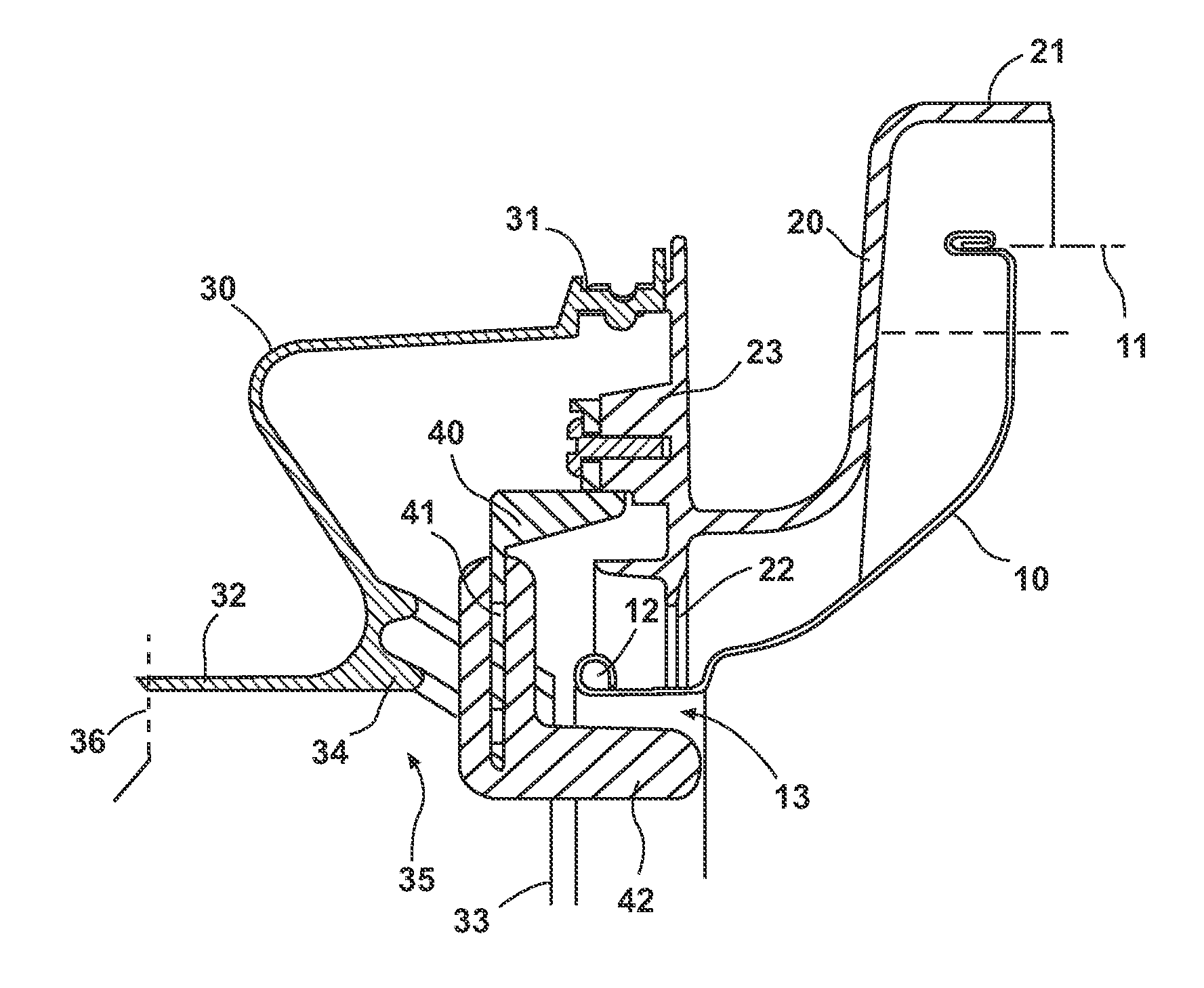
[0016]The cross-sectional view in FIG. 1 shows the upper front region of the drum 10, the drum wall 11 of which is held in an end part forming the filler opening 12 with a reduced diameter. This drum 10 is rotatably mounted in the closed rear part of a container 20 in known manner. This container 20 is integral with the housing and surrounds the drum 10 at a spacing therefrom, as the container wall 21 shows. These parts and their function do not need to be described more fully in connection with the present invention. It should only still be mentioned that the holding capacity of the drum 10 has been increased more and more, and that today appliances are quite commonplace which have a quantity of laundry to be inserted of up to about 9 kg or about 20 lbs.

[0017]The front end part of the drum 10 protrudes through the front opening 22 of the container 20. A radial mounting flange 23 extends radially outwardly in the region of the front opening 22 and allows the mounting of an elastic s...


PUM


Abstract

The invention relates to a laundry treatment machine, more especially a washing machine or a laundry dryer, comprising a drivable drum which accommodates laundry and is rotatably mounted in a container integral with the housing, wherein the container is provided with an elastic sleeve, covering the transition from the front opening of the container to the housing opening, around the filler opening of the drum, and wherein a laundry rejector is attached in this transitional region in the region of the top dead center of the drum. For improvement purposes, a specially configured laundry rejector is provided in the region of the top dead center of the drum in conjunction with a receiving means in the sleeve in order to avoid laundry items from becoming damaged.

Description

BACKGROUND OF THE INVENTION[0001]1. Field of the Invention[0002]The invention relates to a laundry treatment machine, more specifically a washing machine or a laundry dryer, comprising a drivable drum which accommodates laundry and is rotatably mounted in a container integral with the housing. The container is provided with an elastic sleeve, covering the transition from the front opening of the container to the housing opening and around the filler opening of the drum. A laundry rejector is attached in the transitional region at the top center of the drum.[0003]2. Description of the Related Art[0004]In laundry treatment machines, more and more demands are being made on the laundry holding capacity of the machine. These demands lead to the dimension between the bottom of the drum and the lower region of the filler door becoming smaller and smaller with larger filler doors. The lower region of the filler door and that of the sleeve often lie on the same plane. This means that the lau...

Claims


Application Information

Patent Timeline
14 Aug 2007
Publication
US7254970B2
IPC
D06F39/14; D06F37/26
CPC
D06F37/26; D06F37/266
Inventors
BUSS, KARL-HEINZ; MAENTELE, GERD