Gas heat exchanger

a heat exchanger and gas technology, applied in the direction of stationary tubular conduit assembly, exhaust gas recirculation, fuel addition to non-fuel substances, etc., can solve the problems of undesirable gas cooling, undesirable further warming, undesirable gas cooling, etc., to reduce contact and reduce undesirable heat exchange

Active Publication Date: 2007-08-14
SENIOR IP GMBH
View PDF12 Cites 17 Cited by
  • Summary
  • Abstract
  • Description
  • Claims
  • Application Information

AI Technical Summary

Benefits of technology

[0015]It is an object of the present invention to provide an improved exhaust gas recirculation cooler that does not require an external bypass channel, or does not necessarily require a coolant valve for selecting whether or not coolant fluid flows through the coolant channel. The inventors have realised the problems associated with prior art gas heat exchanges with bypass conduits, and have devised a gas heat exchanger in which the gas cooling conduit is disposed between the bypass conduit and the coolant conduit, thereby reducing a contact between the bypass conduit and the coolant conduit. This reduces any undesirable heat exchange between the bypass conduit and the coolant conduit, as the gas cooling conduit acts as a thermal barrier between the coolant conduit and the bypass conduit.

Problems solved by technology

Under some circumstances, heat exchange may be required, but under other circumstances it may be undesirable.
However, once the cabin reaches the required temperature, further warming could be undesirable.
Cooling the EGR gas is not desirable under all conditions however.
When gas is being transported through the bypass conduit, it is undesirable for the gas to be cooled.
The external bypass channel takes up additional space, which is a disadvantage for applications where packaging in the engine space is restricted.
However, this solution is used because the bypass conduit is external to the exhaust gas cooling conduit and the coolant conduit and therefore the bypass conduit is not cooled by the coolant conduit.
The bypass conduit is therefore in contact with the coolant in this type of cooler, which is undesirable.
Another disadvantage of a bypass conduit is that the material in the bypass conduit acts as a heat sink when hot EGR gas is diverted through it.
However, there are problems with this type of system.
The formation of steam and volatile substances is not desirable.

Method used


Image

  • Gas heat exchanger
  • Gas heat exchanger
  • Gas heat exchanger

Examples


Embodiment Construction

[0075]There will now be described by way of examples several specific embodiments contemplated by the inventors. In the following description numerous specific details are set forth in order to provide a thorough understanding. It will be apparent however, to one skilled in the art, that the present invention may be practiced without limitation to these specific details.

[0076]Throughout the description, the following terms are used:

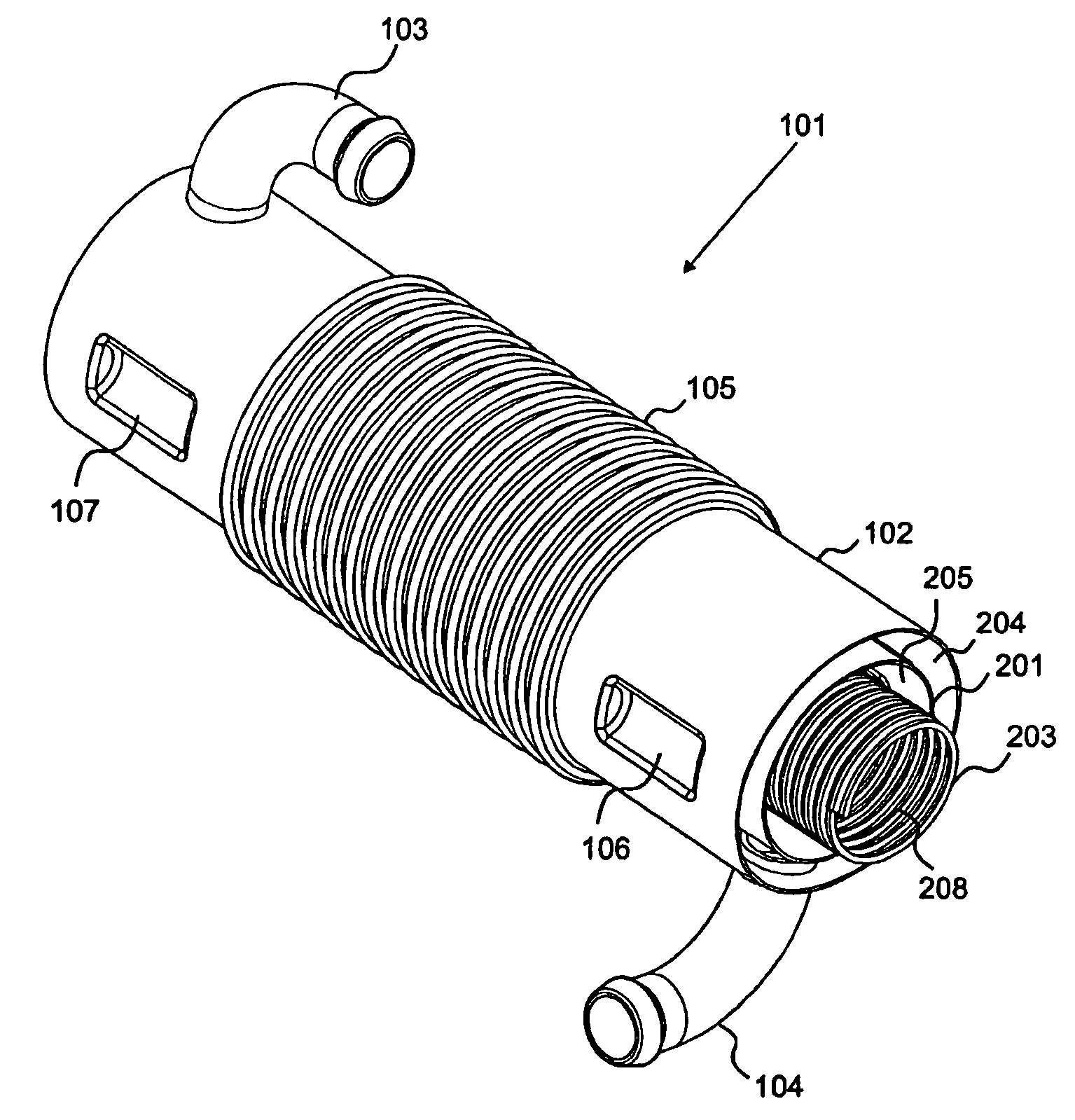
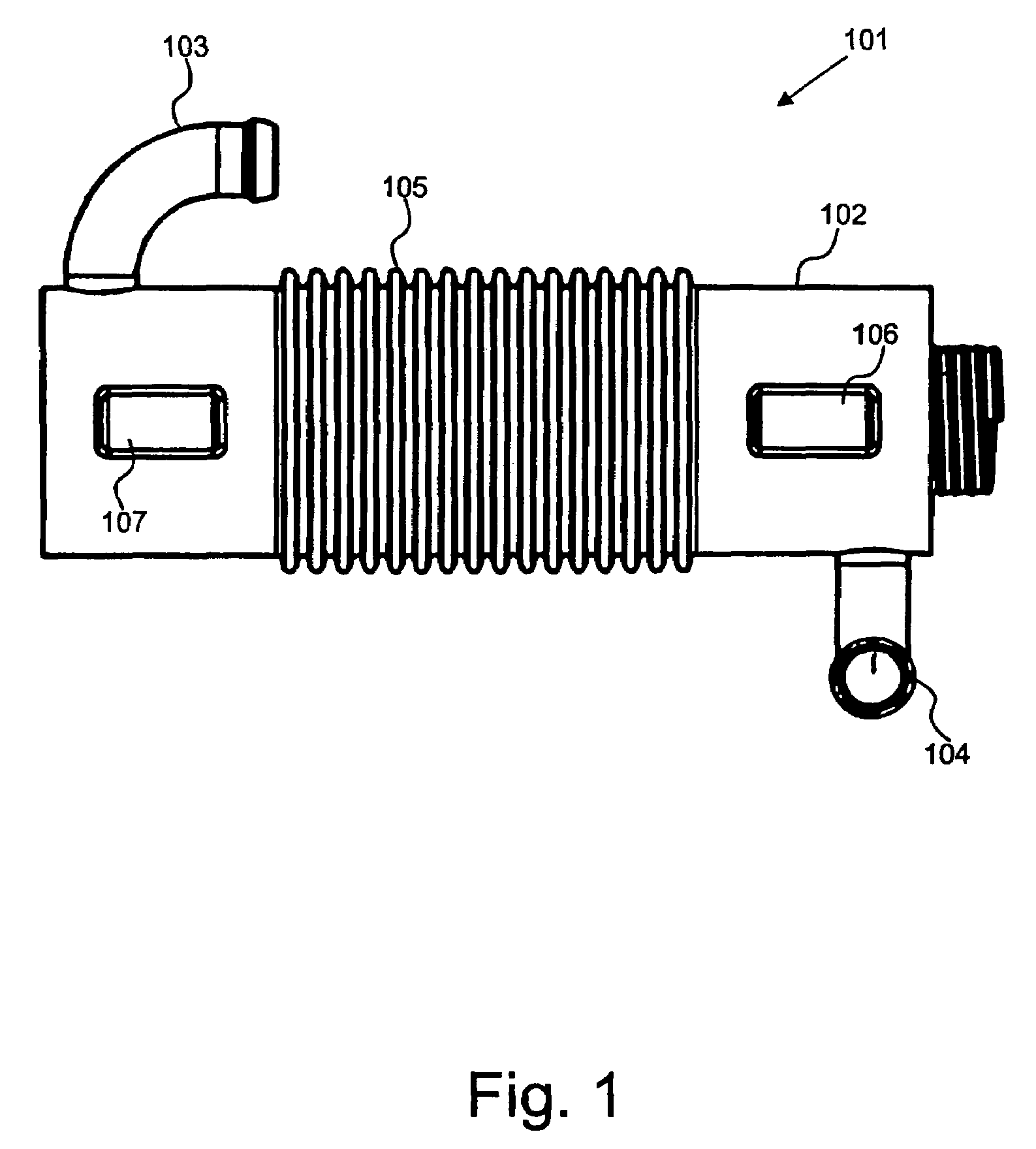
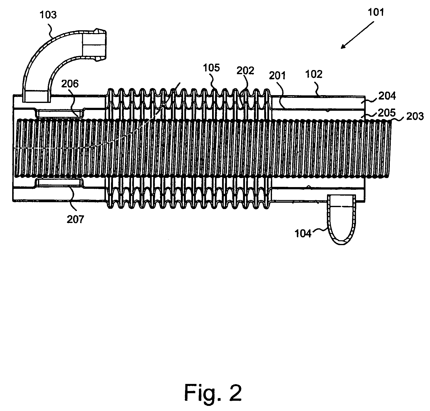
[0077]‘Gas cooling conduit’ refers to a conduit through which gas is configured to pass when heat extraction from the gas is required.

[0078]‘Coolant conduit’ refers to a conduit through which coolant medium such as coolant fluid is configured to pass. A coolant medium may be used to reduce the temperature of the gas in the gas cooling conduit, or may be used to extract heat from the gas in the gas cooling conduit to be used elsewhere.

[0079]‘Bypass conduit’ refers to a conduit through which gas is configured to pass when heat extraction from the gas is not...


PUM


Abstract

There is provided a gas heat exchanger 101 comprising a coolant conduit 102 having a coolant inlet 103 and a coolant outlet 104, a gas cooling conduit 201, and a gas bypass conduit 203. At least a portion of the gas cooling conduit 201 is disposed between at least a portion of the coolant conduit 102 and a portion of the bypass conduit 203. During a first mode of operation, the gas cooling conduit 201 is configured to carry gas. During a second mode of operation, the bypass conduit 203 is configured to carry gas and the gas cooling conduit 201 is configured to reduce a heat exchange between the coolant conduit 102 and the bypass conduit 203.

Description

BACKGROUND OF THE INVENTION[0001]1. The Technical Field[0002]The present invention relates to gas heat exchangers.[0003]2. The Prior Art[0004]There are many applications in which it is desirable to use gas heat exchangers. These include applications where it is desired to cool down a gas, for example in exhaust gas recirculation (EGR) coolers, and applications in which the heat extracted from the gas can be recovered, for example to warm the cabin of a vehicle.[0005]Under some circumstances, heat exchange may be required, but under other circumstances it may be undesirable. For example, at the beginning of operation of a vehicle, heat may be extracted from exhaust gas to assist in warming up the cabin of a vehicle. In this case, heat extraction is required. However, once the cabin reaches the required temperature, further warming could be undesirable. Therefore under these circumstances, heat extraction is not required.[0006]Another example is exhaust gas recirculation. Exhaust gas ...

Claims


Application Information

Patent Timeline
Patent Type & Authority Patents(United States)
IPC IPC(8): F02M25/07F02B47/08F28F27/02G05D23/00F28D7/10F28F1/08F28F21/08
CPCF02M25/0728F02M25/0737F28D7/103F28F1/08F28F21/082F28F27/02F28F2250/06Y02T10/121F28F2240/00F28F2265/26F02M26/25F02M26/32F28F21/083F02M26/00F28D7/10F28D7/16
Inventor CRAIG, IAN ANTHONYCHALLIS, RAYMOND WILLIAMPENNY, CHARLES JAMESDOWNS, PAULHACKER, MARK ROBERT
Owner SENIOR IP GMBH
Why Eureka
Try Eureka