Convertible rotary seal for progressing cavity pump drivehead

a technology of rotary seals and driveheads, which is applied in the direction of wells, well casings, drilling pipes, etc., can solve the problems of time-consuming and untimely procedures, failure to detect rsu, etc., and achieve convenient field operations, avoid costly addition shut-down, and eliminate the effect of polish rod wear

Active Publication Date: 2007-08-14
RAVDOS HLDG INC
View PDF16 Cites 26 Cited by
  • Summary
  • Abstract
  • Description
  • Claims
  • Application Information

AI Technical Summary

Benefits of technology

[0005]The rotary seal unit (“RSU”) of the invention is characterized by seal elements, such as lip seals, that run on a rotating mandrel. By utilizing a rotating mandrel the polish rod is isolated from running elements, which eliminates wear of the polish rod. A top part of the mandrel has a chamber containing a poly seal that seals and grips the polish rod. The polish rod drives the mandrel, which is sealed by multiple lip seals. The space between the multiple lip seals communicates through various machined holes and cavities with an exterior port. An operator may open the exterior port to check for fluid. A fluid presence proximate the exterior port indicates a failure of one or more of the lower lip seals. Thus, the failure of the RSU may be detected before well fluid leakage occurs.
[0006]Replacement of a drivehead rotary seal requires removal of the drivehead, which can be a time consuming and perhaps untimely procedure. The RSU of the invention allows for the drivehead to be shut down and for the mandrel to be locked to the body of the RSU. The top seal, e.g., a poly seal, may then be replaced by a stationary seal such as Teflon and graphite packing. Once the packing is installed, the top seal becomes static. In this way the RSU of the invention may be operated as a conventional stuffing box until replacement of the RSU is convenient to field operations.
[0007]Advantages of the RSU of the invention include utilizing multiple lip seals as a primary seal and utilizing a secondary static seal that includes conventional poly-style packing. The system of the invention provides an early warning in advance of a primary seal failure. In the event of a primary seal failure, the secondary seal can be converted to avoid an unscheduled shutdown of the pumping system. The secondary sealing system operates as a conventional stuffing box using Teflon and graphite packing that can continue to be utilized until a maintenance event can be scheduled, thus avoiding a costly addition shut-down.
[0008]An added benefit of the RSU of the invention is reduced polished rod wear. The primary seals are designed so that while in operation the wear to the polished rod is reduced or eliminated.

Problems solved by technology

Thus, the failure of the RSU may be detected before well fluid leakage occurs.
Replacement of a drivehead rotary seal requires removal of the drivehead, which can be a time consuming and perhaps untimely procedure.

Method used


Image

  • Convertible rotary seal for progressing cavity pump drivehead
  • Convertible rotary seal for progressing cavity pump drivehead
  • Convertible rotary seal for progressing cavity pump drivehead

Examples


Embodiment Construction

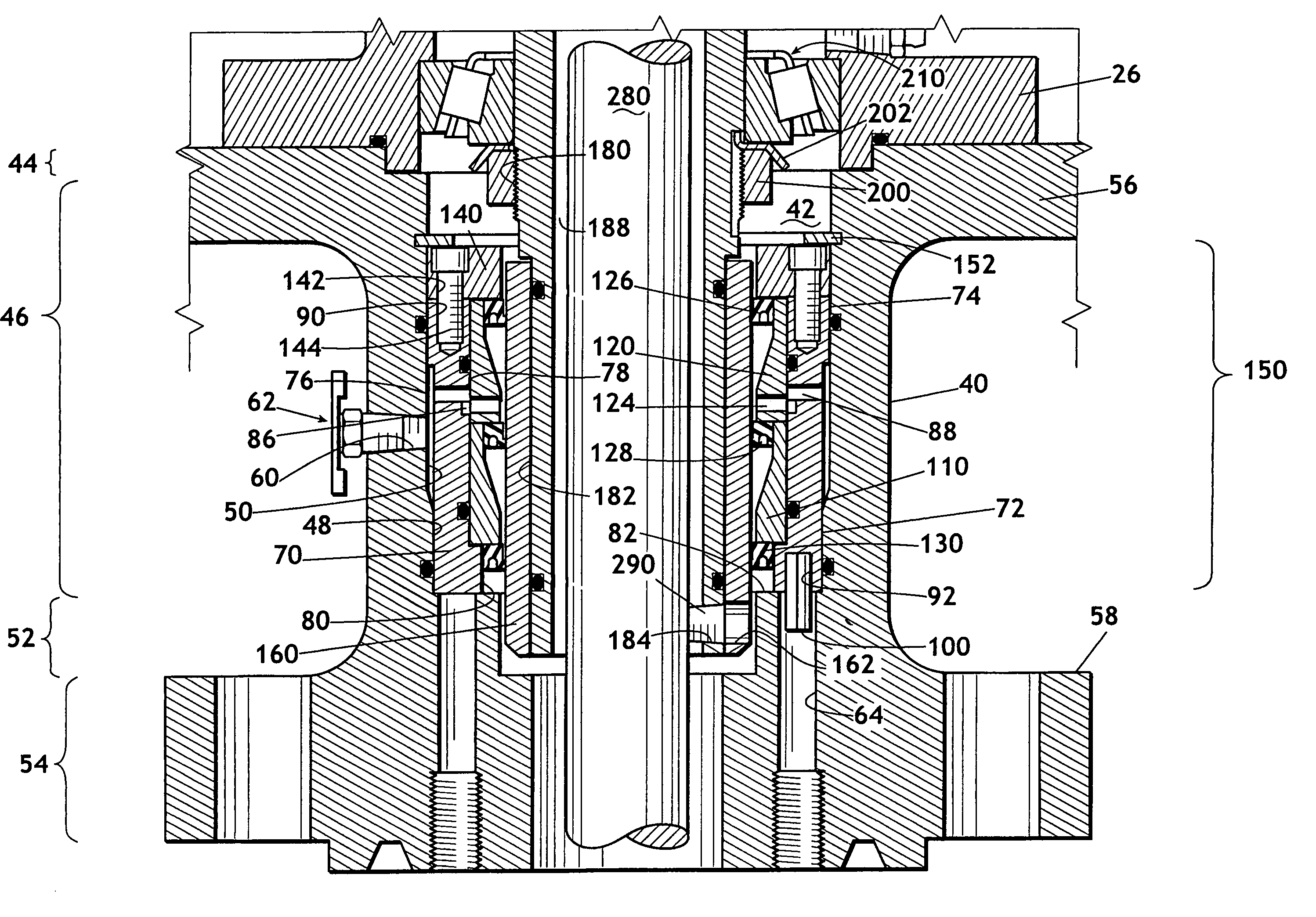
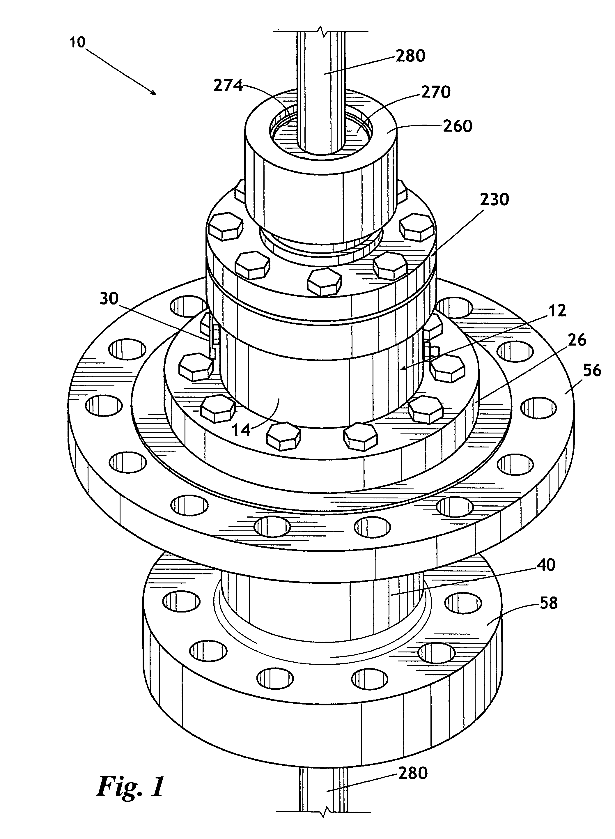
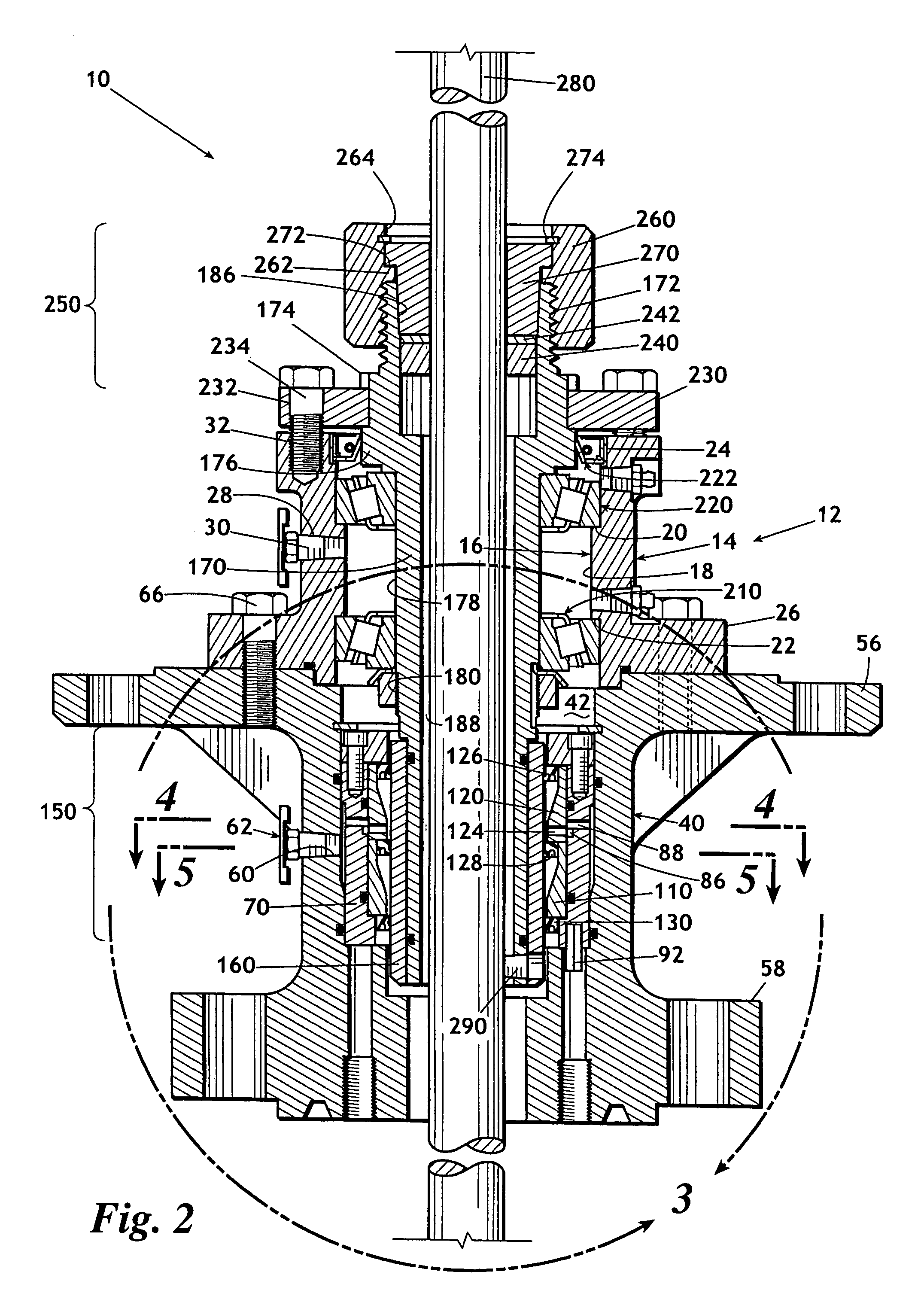
[0014]Referring now to FIGS. 1-5, rotary seal 10 for a progressive cavity pump drivehead is shown. Rotary seal 10 includes a housing 12. Housing 12 is preferably made up of a bearing housing 14 (FIGS. 1 and 2) and a seal housing 40. Bearing housing 14 defines an inside surface 16 having an interior ring 18 (FIG. 2). Interior ring 18 defines an upper shoulder 20 and a lower shoulder 22. Bearing housing 14 defines an upper diameter 24 and a lower flange 26. Bearing housing 14 additionally defines an orifice 28 that receives an upper breather petcock 30 (FIGS. 1 and 2). Bearing housing 14 further defines a plurality of bolt receiving holes 32 and an upper surface of the bearing housing 14.

[0015]As can best be seen in FIG. 3, housing 12 additionally is made up of seal housing 40 (FIGS. 1-5). Seal housing 40 defines an interior cavity 42 (FIGS. 2 and 3) having a first or mating section 44 of a first diameter, a second or seal section 46 having a lower diameter 48 and a larger upper diame...


PUM


Abstract

A convertible rotary seal has a housing for receiving a polish rod. A mandrel is rotatably mounted in the seal housing and surrounds the polish rod. A wear sleeve surrounding the mandrel engages a primary seal. A secondary seal engages the mandrel and polish rod and rotates therewith but may be converted for use as a static seal if necessary. A locking mechanism selectively secures the mandrel in a stationary orientation with respect to the seal housing. Fluid that leaks past the primary seal will be detectible through an external orifice. If a leak in the primary seal is detected via the external port, then the mandrel may be secured in a stationary orientation with respect to the housing and the secondary seal may be reconfigured to operate as a stationary seal until such time as the rotary sealing unit can be overhauled.

Description

FIELD OF THE INVENTION[0001]This invention relates generally to a wellhead stuffing box for sealing engagement with a polish rod. More particularly, the invention relates to a stuffing box having a primary and a secondary seal for use with a rotating polish rod.BACKGROUND OF THE INVENTION[0002]In a standard wellhead, a stuffing box is used to provide a rotary seal around the polish rod of a rod string, which is used to drive a downhole pump. A typical stuffing box is constructed of a generally tubular housing that is threaded onto an upwardly projecting portion of a wellhead. The polish rod extends through the wellhead and through the stuffing box housing. An annular space is formed between stuffing box housing and the polish rod. Typically, a stack of compressible packing rings are positioned in the annular space to form a seal around the polish rod. An internal radial shoulder in the stuffing box housing supports the packing rings at a bottom end of the stack. An annular packing g...

Claims


Application Information

Patent Timeline
Patent Type & Authority Patents(United States)
IPC IPC(8): E21B19/00E21B33/02
CPCE21B33/085E21B43/126
Inventor RIVARD, RAYMOND P.
Owner RAVDOS HLDG INC
Why Eureka
Try Eureka