
Air suspension system for vehicle

a suspension system and air suspension technology, applied in the direction of resilient suspensions, vehicle components, transportation and packaging, etc., can solve the problems of large air pressure loss, low responsiveness, complicated entanglement of the line through which air flows, etc., to enhance responsiveness, enhance the efficiency of an air drier, and minimize the effect of air pressure loss

Active Publication Date: 2007-08-14
HYUNDAI MOBIS CO LTD
View PDF3 Cites 21 Cited by
  • Summary
  • Abstract
  • Description
  • Claims
  • Application Information

AI Technical Summary

Benefits of technology

[0009]The present invention has been made to solve the above problems, and it is an object of the present invention to provide an air suspension system for a vehicle designed to minimize loss of air pressure, to enhance responsiveness, and to enhance efficiency of an air drier.

Problems solved by technology

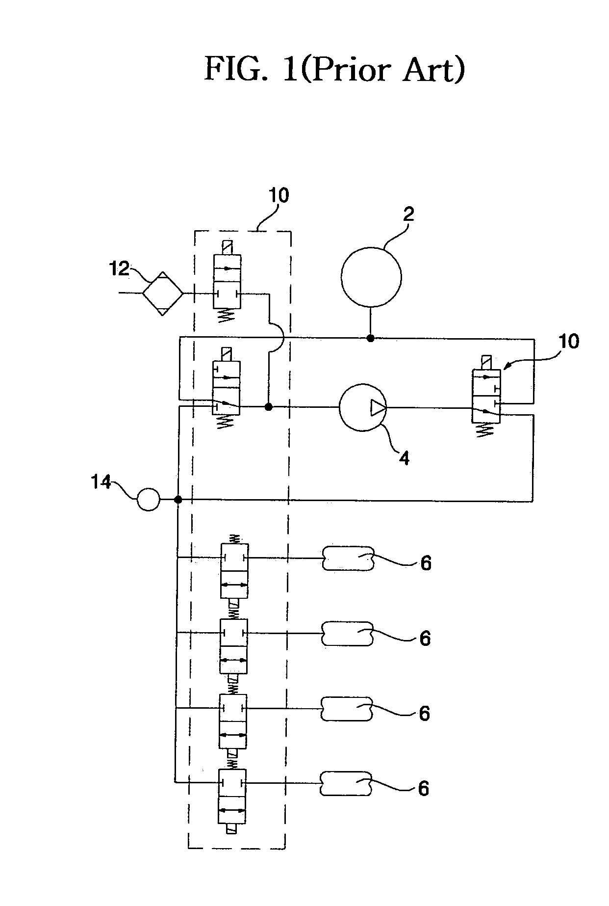
However, in the conventional air suspension system for the vehicle disclosed above, the air tank 2 and the air spring 6 are not connected to each other by means of an in-line structure, and the line through which air flows is complicatedly entangled.
As a result, there occur problems of a large air pressure loss and of low responsiveness.
As a result, there occur problems in that the air drier 12 has a large volume, and in that the air drier 12 is excessively operated, causing ineffective operation of the air drier 12.

Method used


Image

  • Air suspension system for vehicle
  • Air suspension system for vehicle
  • Air suspension system for vehicle

Examples


Embodiment Construction

[0025]Embodiments of an air suspension system for a vehicle according to the present invention will now be described in detail with reference to the accompanying drawings.

[0026]Although various embodiments of the air suspension system for the vehicle according to the present invention can be provided, a most preferred embodiment will be described in the specification. Since a basic configuration of the air suspension system for the vehicle is the same as that of the conventional air suspension system described above, detailed description thereof will be omitted.

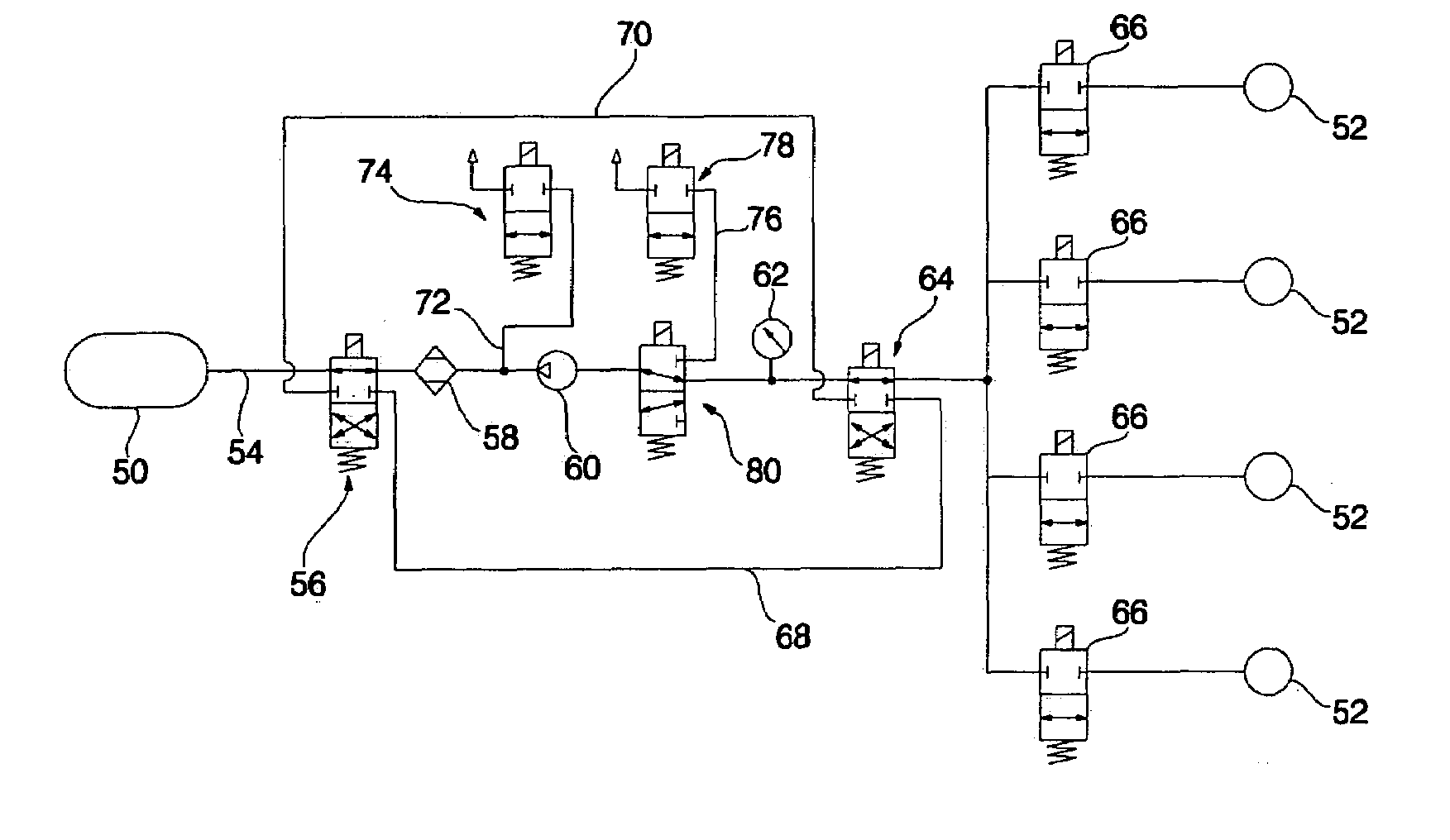
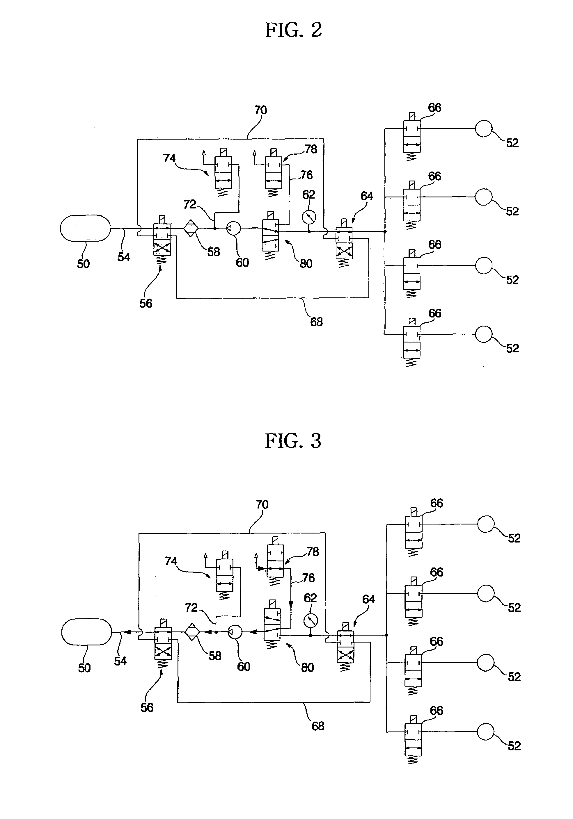
[0027]FIG. 2 is a circuit diagram of an air suspension system for a vehicle according to the present invention.

[0028]An air suspension system for a vehicle according to the present invention comprises: a first line 54 provided between an air tank 50 and an air spring 52; a first valve means 56, an air drier 58, a compressor 60, a pressure meter 62, a second valve means 64, and an air spring-opening / closing valve 66, sequentia...


PUM


Abstract

An air suspension system includes an air tank, an air drier, a compressor, and an air spring, which are sequentially provided in a first line. The air suspension system further includes a second line, a third line, an intake line, and a discharge line, which are connected to the first line. The first line, the second line and the third lines can be switched by a 4-port / 2-position solenoid valve, and the first line is selectively connected to the intake line by a 3-port / 2-position solenoid valve.

Description

BACKGROUND OF THE INVENTION[0001]1. Field of the Invention[0002]The present invention relates to an air suspension system for a vehicle, and more particularly to an air suspension system for a vehicle designed to allow air to circulate in a closed circuit between an air tank and a spring.[0003]2. Description of the Related Art[0004]FIG. 1 is a circuit diagram of a conventional air suspension system for a vehicle.[0005]The conventional air suspension system for the vehicle serves to allow air in an air tank 2 to be supplied to an air spring 6, or to allow air to be withdrawn from the air spring 6 to the air tank 2 by means of a compressor 4 via several valve means 10 provided among the air tank 2, the compressor 4, and the air spring 6, respectively. Furthermore, the air suspension system allows outside air to be added to the air tank 2 or allows air in the air tank 2 to be discharged to the outside via the valve 10.[0006]Meanwhile, an air drier 12 to dry air is equipped in a line th...

Claims


Application Information

Patent Timeline
Patent Type & Authority Patents(United States)
IPC IPC(8): B60G11/27
CPCB60G17/0155B60G17/0528B60G17/056B60G17/044
Inventor KIM, HAN SOO
Owner HYUNDAI MOBIS CO LTD
Learn More