Turbine airfoil platform cooling circuit

a technology of cooling circuit and turbine airfoil, which is applied in the direction of machines/engines, stators, mechanical equipment, etc., can solve the problems of platform oxidation, platform wall creep deformation, thermal-mechanical fatigue, etc., and achieves the effect of increasing internal heat transfer coefficient, increasing cooling surface area, and enhancing cooling

Active Publication Date: 2007-08-14
RTX CORP
View PDF8 Cites 64 Cited by
  • Summary
  • Abstract
  • Description
  • Claims
  • Application Information

AI Technical Summary

Benefits of technology

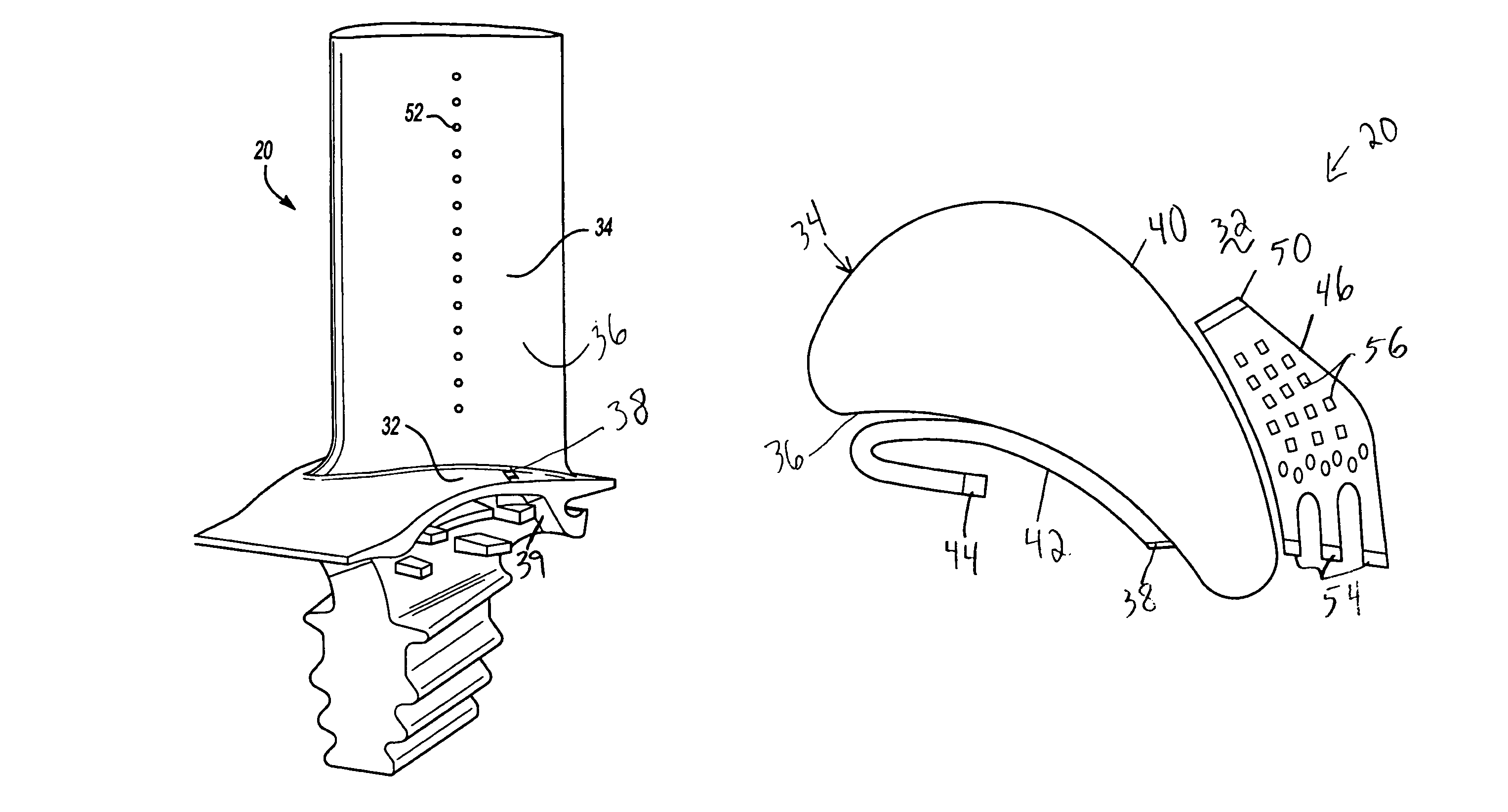
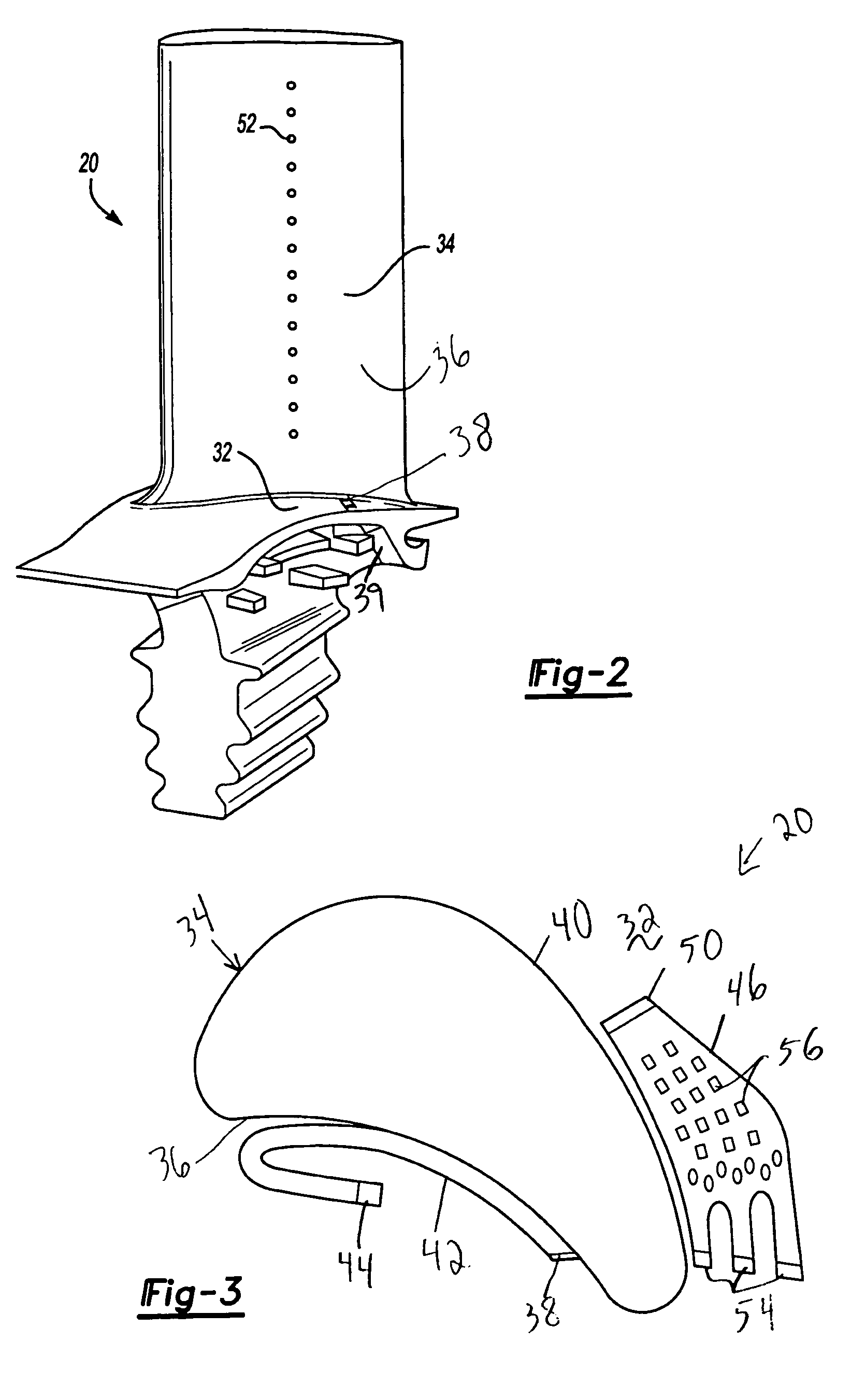
[0007]Optionally, at least the suction side of the cooling circuit includes a plurality of pedestals extending between top and bottom walls of the cooling circuit. The pedestals are positioned inside the circuit to provide structural integrity and stiffness for the platform. The pedestals also turbulate the flow and enhance cooling by increasing the internal heat transfer coefficients. The pedestals also provide increased surface area for cooling and provide conduction paths between the outer and inner wall of the cooling circuit.
[0008]The exit of each cooling circuit drives the cooling air in such a way as to provide the film coverage on the platform. This film blanket of cooling air further protects the platform walls from the hot gas recovery temperatures.

Problems solved by technology

Without sufficient cooling of the platform, the platform walls may experience creep deformation.
High temperature gradients in the platform may result in thermal-mechanical fatigue.
Additionally, the high temperatures can cause oxidation of the platforms.

Method used


Image

  • Turbine airfoil platform cooling circuit
  • Turbine airfoil platform cooling circuit
  • Turbine airfoil platform cooling circuit

Examples


Embodiment Construction

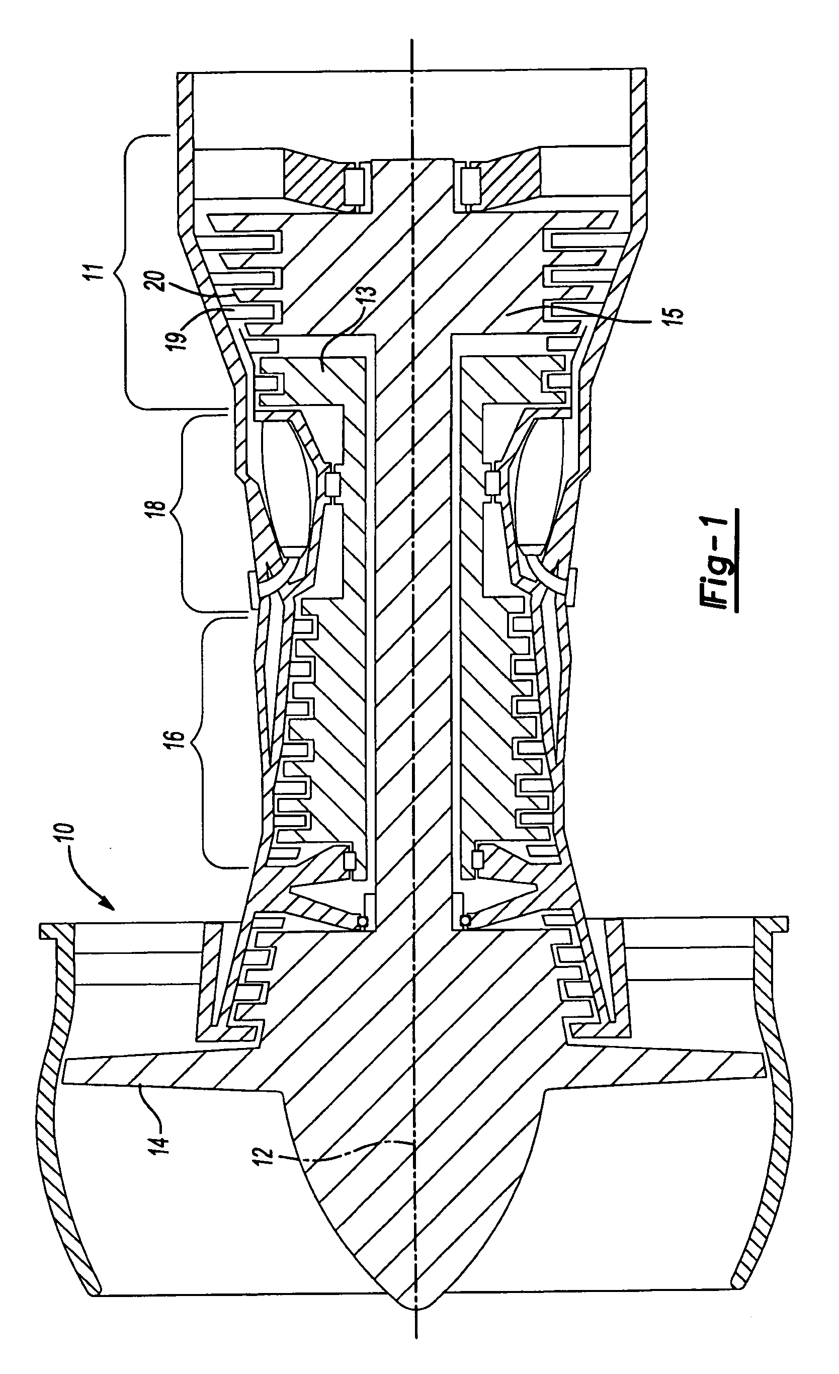
[0015]FIG. 1 shows a gas turbine engine 10, such as a gas turbine used for power generation or propulsion, circumferentially disposed about an engine centerline or axial centerline axis 12. The engine 10 includes a fan 14, a compressor 16, a combustion section 18 and a turbine 11. As is well known, air compressed in the compressor 16 is mixed with fuel that is burned in the combustion section 18 and expanded in turbine 11. The turbine 11 includes rotors 13 and 15 that rotate in response to the expansion, driving the compressor 16 and fan 14. The turbine 11 compresses alternating rows of turbine blades 20 and vanes 19. FIG. 1 is a somewhat schematic presentation for illustrative purposes only and is not a limitation on the instant invention, which may be employed on gas turbines for electrical power generation, aircraft, etc. Additionally, there are various types of gas turbine engines, many of which could benefit from the present invention, which is not limited to the design shown.

[...


PUM


Abstract

An airfoil assembly includes an airfoil extending away from a platform. One or more cooling circuits are formed through the platform in order to provide cooling of the platform. The cooling circuit may include a downwardly directed inlet receiving cooling air from below the platform. The cooling air is then directed in a direction generally parallel to the outer surface of the platform and through exits formed through the outer surface of the platform. The cooling circuit may optionally include a plurality of pedestals extending from an outer wall to an inner wall of the cooling circuit to increase the rigidity and the cooling function of the cooling circuit.

Description

[0001]This invention was made with Government support under F33615-03-D-2354 awarded by the United States Air Force. The Government has certain rights in this invention.BACKGROUND OF THE INVENTION[0002]The present invention relates generally to gas turbine engines and more particularly to a cooling circuit for a platform of a turbine airfoil.[0003]Turbine blades in a gas turbine engine extend outwardly from a turbine blade platform. In operation, the turbine blades are routinely exposed to temperatures well above their material limits. In existing engines, air from the compressor section of the turbine engine is used to cool the blade material. This cooling air is fed to the blade through a series of rotor cavities underneath the blade platform. The cooling air is then injected into the hot mainstream flow through openings in the sealing area.[0004]Without sufficient cooling of the platform, the platform walls may experience creep deformation. High temperature gradients in the platf...

Claims


Application Information

Patent Timeline
Patent Type & Authority Patents(United States)
IPC IPC(8): F01D5/18
CPCF01D5/18F01D9/02F01D25/12Y02T50/676F05D2260/208F05D2240/81F01D5/187Y02T50/60F01D5/00F01D5/08F02C7/12
Inventor CUNHA, FRANK J.COUCH, ERICSANTELER, KEITH A.GAYMAN, SCOTT W.HUDSON, ERIC A.JOE, CHRISTOPHERLETIZIA, ERIC
Owner RTX CORP
Why Eureka
Try Eureka