Connector device

a technology of connecting devices and connectors, applied in the direction of coupling contact members, coupling device connections, printed element electric connection formation, etc., can solve the problem of easy falling off of card members, and achieve the effect of improving electric contact, simple lock structure, and reducing the cost of manufacturing connectors with lock structures

Inactive Publication Date: 2007-08-14
NEC CORP
View PDF48 Cites 25 Cited by
  • Summary
  • Abstract
  • Description
  • Claims
  • Application Information

AI Technical Summary

Benefits of technology

[0006]In recent years, electronic devices have been downsized. Connector devices to be mounted on electronic devices have hence been required to be downsized. To realize a connector device having a smaller size, for example, the connector device uses in many cases a serial transmission technique in place of using a conventional parallel transmission technique. This increases the signal transmission speed transmitted through the connector device.
[0010]According to the connector device of the present invention, a lock structure can be realized which locks together the plug and the socket by using the protrusion or recess which is formed on the contact surface of the plug terminal and by using the recess or protrusion which is elastically urged against and engaged with the protrusion or recess of the plug terminal. Since the lock structure is formed at the contact surfaces contacting the plug terminal with the socket terminal, the connector device having the lock structure can be downsized without enlarging the connector device for the space of the lock structure. In addition, the connector device has a simple lock structure, and therefore, the costs necessary for manufacturing the connector having the lock structure can be reduced. Moreover, the lock structure improves the electric contact between the plug terminal and the socket terminal.

Problems solved by technology

Particularly, the latter type has a problem in that the card member easily falls off when the cable connected to the socket is pulled by an external force.

Method used


Image

  • Connector device
  • Connector device
  • Connector device

Examples


Embodiment Construction

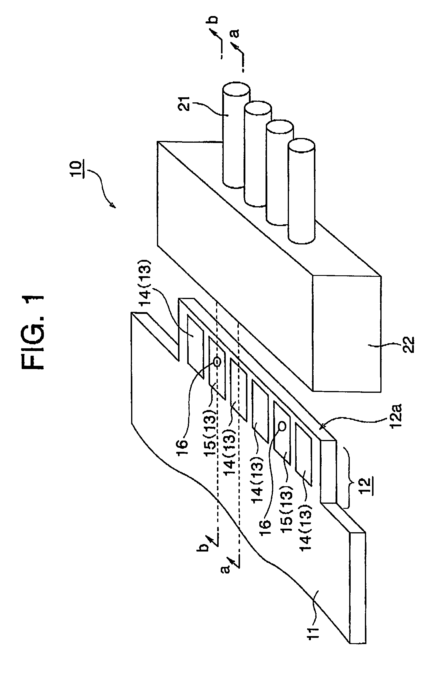
[0015]Referring to the accompanying drawings, the present invention will now be described in detail below on the basis of an embodiment of the present invention. FIG. 1 is a perspective view showing the structure of a connector device according to the embodiment. The connector device, generally designated by numeral 10, is a card edge connector, and is configured by a combination of plug 12 and socket 22. At an edge portion of a card member 11 configured by a multilayer printed circuit board, the plug 12 is provided as a part of the multilayer printed circuit board. The socket 22 is connected to an end portion of a cable 21.

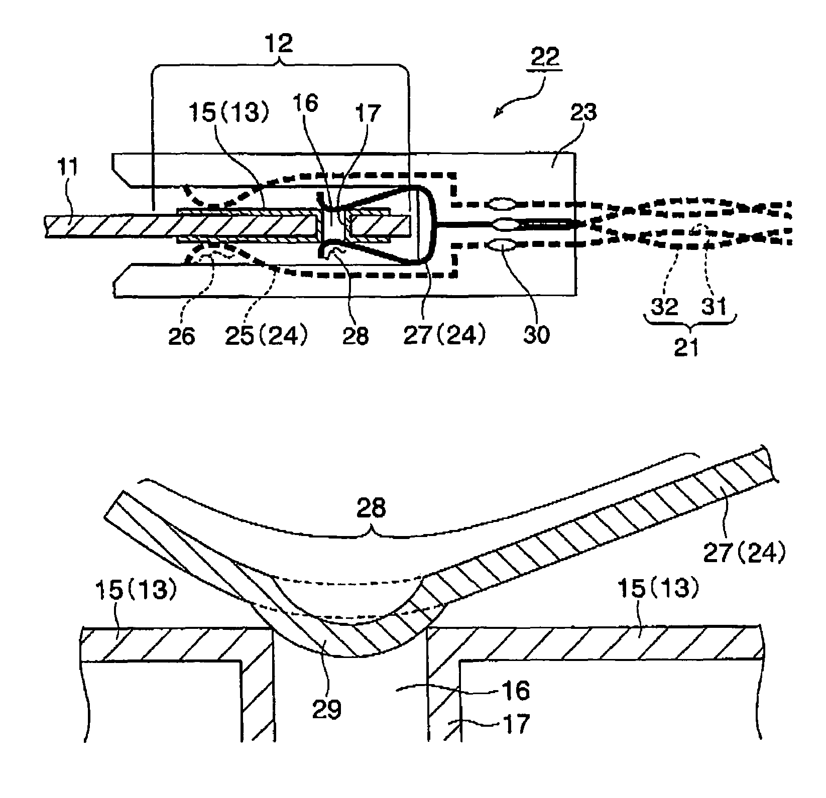
[0016]On both board surfaces of the plug 12, a plurality of pad electrodes (plug terminals) 13 are provided. The pad electrodes 13 each have a rectangular planar shape which is elongated in the direction of inserting the plug 12 into the socket 22. The pad electrodes 13 each are 2.0 mm long in the direction of the longer edge of the rectangle and 1.5 mm long in t...


PUM


Abstract

A connector device includes a plug including a plurality of plug terminals and a socket including a plurality of socket terminals. Ground plug terminals each have a recess on the contact surface, and ground socket terminals each have a dimple on the contact surface thereof. The dimple of the ground socket terminal is elastically urged to the recess of the ground plug terminal for obtaining a firm electric contact between the ground plug terminal and the ground socket terminal.

Description

BACKGROUND OF THE INVENTION[0001]1. Field of the Invention[0002]The present invention relates to a connector device including a plug and a socket, and particularly to a lock structure for locking together the plug and the socket.[0003]2. Description of the Related Art[0004]A card edge connector includes a combination of a plug including a plurality plug pins (plug terminals) and a socket including a plurality of socket pins (socket terminals). The plug is provided at an edge portion of a card member such as a printed circuit board. The socket pins are connected to an external circuit. The plug terminals of the card member are configured as pad electrodes. The socket terminals are configured as contact electrodes which contact surfaces of the pad electrodes when the plug of the card member is inserted into the socket. In a card edge connector, the pad electrodes are constructed as parts of printed wires of the card member. The card edge connector has a shorter wiring length, compared...

Claims


Application Information

Patent Timeline
Patent Type & Authority Patents(United States)
IPC IPC(8): H01R13/625
CPCH01R13/20H01R23/688H05K1/117H05K3/325H05K3/42H05K2201/09036H05K2201/09481H05K2201/09745H01R13/6597H01R12/721
Inventor OKADA, YOSHIKATSU
Owner NEC CORP
Why Eureka
Try Eureka