Electrical wire connector

a technology of electrical connectors and wires, applied in the direction of contact members penetrating/cutting insulation/cable strands, basic electric elements, electrical equipment, etc., can solve the problems of not being able to consider the true ease of use, not being able and all prior wire connectors failed to provide good electrical conduction and ease of use. , to achieve the effect of maximizing mechanical retention strength and electrical connection, and being cheap to manufactur

Active Publication Date: 2007-08-14
HEAVY POWER
View PDF5 Cites 62 Cited by
  • Summary
  • Abstract
  • Description
  • Claims
  • Application Information

AI Technical Summary

Benefits of technology

[0010]It is therefore an object of the present invention to provide an electrical wire connector for electrically connecting multiple wires together that provides both optimized mechanical retention strength of and electrical connection between the wires while is cheap to manufacture and ensures ease of use via prevention of insertion failure.
[0012]The present invention further provides an electrical wire connector for connecting wires electrically together, the connector having an enclosing means enclosing therein a conduction and retention means mated with a guide and lock means, the guide and lock means having at least one separation wall, the conduction and retention means having at least one resilient spring leg and a conduction plate, the connector comprising at least one wire engagement segment formed by the at least one separation wall, the at least one resilient spring leg and the conduction plate surrounding the wire insertion channel for completely surrounding stripped end of each of the wires inserted thereby preventing the stripped wire end from deflecting out of the wire insertion channel.

Problems solved by technology

Such a dual-role requirement placed limitation to the selection of suitable metallic or alloy material for clips, resulting in the necessity of a compromise between electrical conduction and mechanical retention strength characteristics required for the application.
However, since the contact component also constituted the main and bulk metallic structure for the connector, an optimized material such as copper alloy for the contact component can still be costly for the connector.
However, all these prior wire connectors failed to simultaneously provide good electrical conduction and ease of use while being cheap and simple to manufacture.
For example, while the connector by Cutler et al. provided good mechanical wire retention characteristics and Blaha's busbar-equipped connector achieved improved electrical conduction for the connected wires, all failed to consider the true ease of use.
Although the connector by Cutler et al. did include parallel guide ribs to assist in holding wire end in the correct orientation during insertion, however, vertical height of these ribs were insufficient that there were still the possibility of wire end sideway deflection or bending to result in failed insertion.
This is particularly a problem in the case of multi-threaded wires.
Blaha's busbar connector was not free of this problem as well.
The Blaha connector included rear receptacles for receiving the ends of the inserted wires, however, these receptacles were not helpful at all in preventing the sideway deflection or bending of the wire end during the insertion.

Method used


Image

  • Electrical wire connector
  • Electrical wire connector
  • Electrical wire connector

Examples


Embodiment Construction

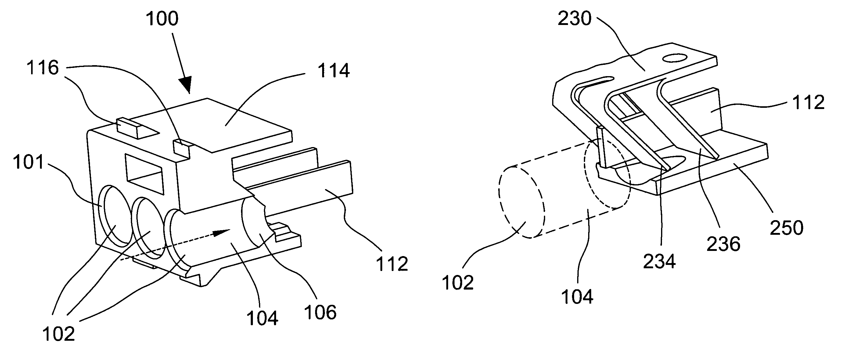
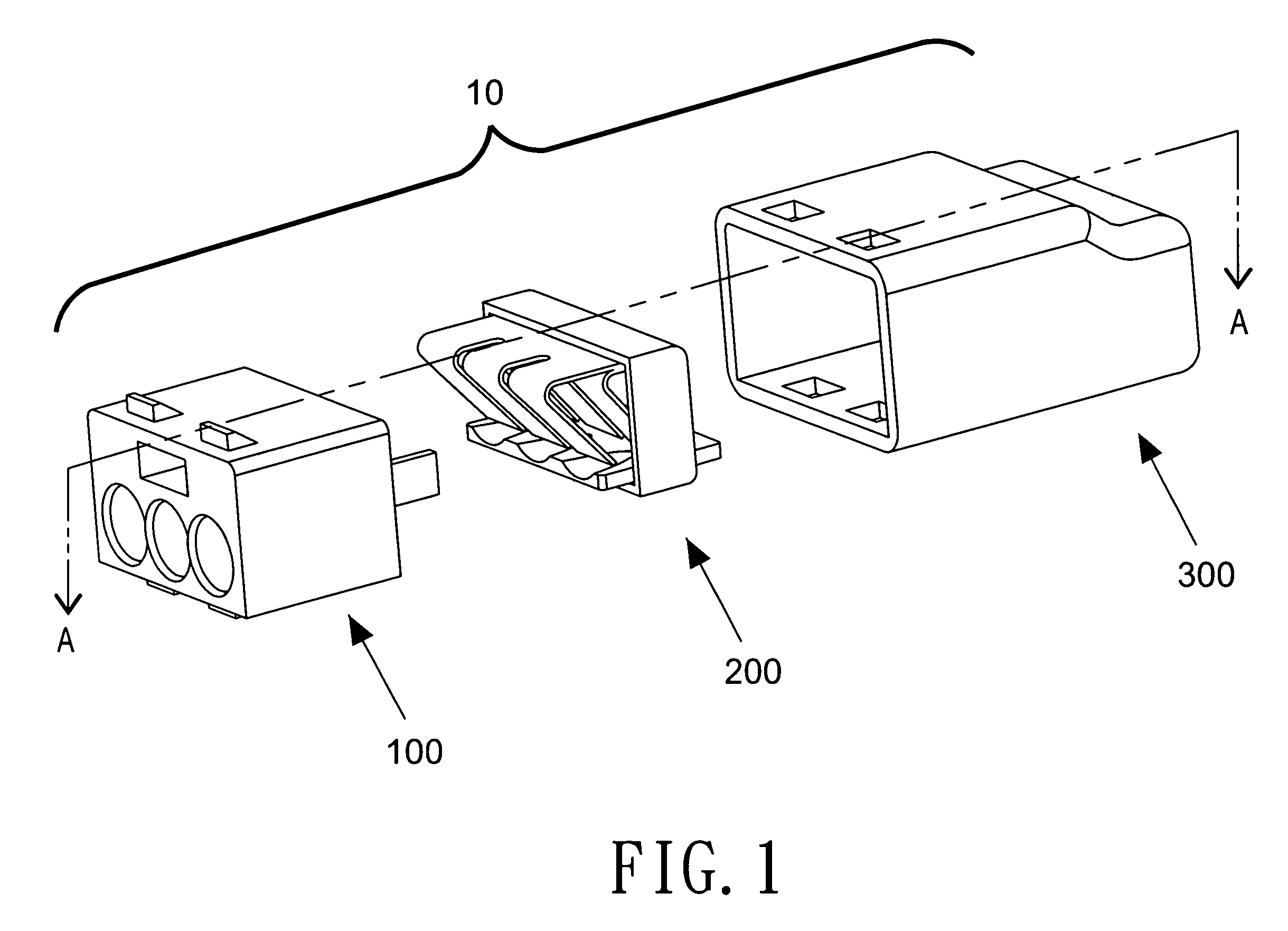
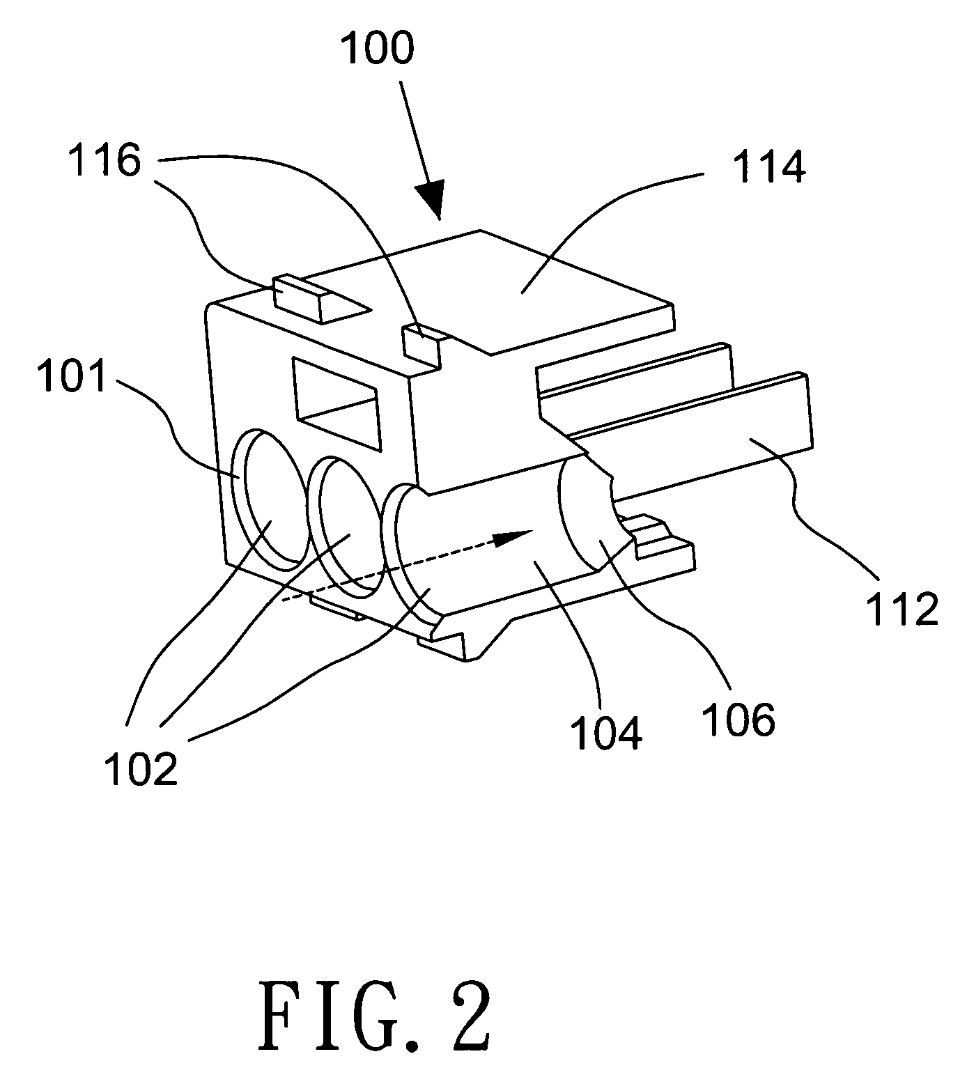
[0020]FIG. 1 is an exploded perspective view of a push-in wire connector in accordance with a preferred embodiment of the present invention. The wire connector 10 comprises three components including a guide and lock element 100, a conduction and retention element 200 and an enclosing element 300. FIG. 6 is a cross-sectional view of an assembled wire connector of FIG. 1. With simultaneous reference to FIGS. 1 and 6, a wire connector 10 according to the preferred embodiment of the present invention is assembled using these three connector elements 100, 200 and 300.

[0021]When assembling, the conduction and retention element 200 mates with the guide and lock element 100 and then the mating slides into the opening of the enclosing element 300 and securedly locked therein as is depicted in the cross-sectional view of FIG. 6. This is clearly illustrated in the cross-sectional view of FIG. 6 by different shading for each of the three elements 100, 200 and 300.

[0022]As an assembled wire con...


PUM


Abstract

A push-in wire connector for electrically interconnecting multiple wires together is disclosed to have a guide and lock element, which is mated with a conduction and retention element and assembled inside the enclosing space of an enclosing element. Multiple wire insertion channels are provided inside the connector for receiving the insertion of wires. Each of the insertion channels includes a main port section led in by an insertion port for guiding the insertion of a stripped end of a wire. A wire engagement segment follows the main portion section formed by the surrounding of a conduction plate at the bottom, an insertion channel separation wall at one or both sides, and the resilient spring legs on the top. The wire engagement segment prevents the bending or deflection of the inserted wire end thereby ensuring secure and good electrical conduction between the inserted wires.

Description

BACKGROUND[0001]1. Field of the Invention[0002]The present invention relates in general to an electrical connector for wires and, more particularly, to a push-in connector for connecting multiple wires electrically together.[0003]2. Description of the Related Art[0004]Push-in wire connectors are useful for connecting multiple wires electrically together in applications including providing utility power gridwork for homes and offices, etc. U.S. Pat. No. 4,824,395 “Push-in wire connector” to Blaha, for example, disclosed a wire connector having a conductive clip of relative simple design for easy fabrication. The clip responsible for providing electrical connection between the connected wires was enclosed in a housing. The clip was made in the form of a cantilever spring so that a wire inserted through an aperture in the housing can deflect the spring and be clamped and retained in the housing. Blaha's wire connector, though simple and easy to manufacture, required its single piece cl...

Claims


Application Information

Patent Timeline
Patent Type & Authority Patents(United States)
IPC IPC(8): H01R4/24
CPCH01R4/22H01R4/4827H01R4/48275
Inventor TSENG, PETER
Owner HEAVY POWER
Why Eureka
Try Eureka