Method of manufacturing nozzle plate

a manufacturing method and nozzle technology, applied in the field of nozzle plate manufacturing, can solve the problems of image deterioration, inability to stabilize the ejection direction of the ink, and the ink ejection efficiency may decline, so as to improve the ejection efficiency. , the effect of high degree of accuracy

Inactive Publication Date: 2007-08-14
FUJIFILM CORP
View PDF7 Cites 5 Cited by
  • Summary
  • Abstract
  • Description
  • Claims
  • Application Information

AI Technical Summary

Benefits of technology

[0015]The present invention is contrived in view of the aforementioned circumstances, an object thereof being to provide a method of manufacturing a nozzle plate that can improve the ejection efficiency and can stabilize the ejection direction and ejection volume.
[0017]According to this aspect of the present invention, a first photosensitive material is formed in the shape of a layer on the substrate, a straight section forming member is placed on the first photosensitive material, and a second photosensitive material is filled into the hole section of the straight section forming member, whereupon exposure is carried out by radiating a prescribed light from the straight section forming member side, the straight section forming member is then removed and a development process is carried out, thereby making it possible to form photosensitive material having a tapered and straight shape on the substrate, with good accuracy. By forming a nozzle plate by plating method, using this photosensitive material as a mold, it is possible to form a tapered and straight-shaped nozzle to a high degree of accuracy. Therefore, the ejection efficiency is improved and the ejection direction and ejection volume are stabilized.
[0019]According to this aspect of the present invention, it is possible to reuse the straight section forming member, and therefore nozzle plates can be manufactured at low cost.
[0021]According to this aspect of the present invention, since the liquid is prevented from adhering to the periphery of the nozzle, then the ejection direction can be further stabilized.
[0022]According to the present invention, a first photosensitive material is formed in the shape of a layer on the substrate, a straight section forming member is placed on the first photosensitive material, and a second photosensitive material is filled into a hole section of the straight section forming member, whereupon exposure is carried out by radiating a prescribed light from the straight section forming member side, the straight section forming member is then removed and a development process is carried out, thereby making it possible to form photosensitive material having a tapered and straight shape on the substrate, with good accuracy. By forming a nozzle plate by plating method, using this photosensitive material as a mold, it is possible to form a tapered and straight-shaped nozzle to a high degree of accuracy. Therefore, the ejection efficiency can be improved and the ejection direction and ejection volume can be stabilized.

Problems solved by technology

In a print head of this kind, if dimensional accuracy is poor in terms of the shape and position of the nozzles formed in the nozzle plate, or the like, then variations occur in the size (volume) of the ink droplets, their direction of flight and their speed of flight.
Consequently, image deterioration may occur and the ink ejection efficiency may decline.
However, there are problems of the following kinds in the above methods of manufacturing nozzle plates.
In the method disclosed in Japanese Patent Application Publication No. 2001-329392, there is no straight section in the nozzles and the ink ejection direction is not stable.
Furthermore, since a tapered electroforming mold is used, then if there is variation in the thickness of the electroforming film, albeit a very slight variation, this could cause variation in the nozzle diameters, and hence lead to a decline in ejection efficiency.
In the method disclosed in Japanese Patent Application Publication No. 5-193144, resin material (dry film) is disposed on the ink flow channel side, and there is a possibility that problems with the resistance to ink may arise.
In the method disclosed in Japanese Patent Application Publication No. 2002-154210, since exposure steps are required to be performed twice, positional displacement can readily occur between the steps, leading to a decline in the dimensional accuracy of the nozzles, which in turn causes a decline in the ejection efficiency and fluctuation in the ejection direction.
In the method disclosed in Japanese Patent Application Publication No. 10-166595, since the nozzles have an overhang shape, variation in the nozzle diameter is liable to occur and it is difficult to stabilize the ink ejection direction.

Method used


Image

  • Method of manufacturing nozzle plate
  • Method of manufacturing nozzle plate
  • Method of manufacturing nozzle plate

Examples


first embodiment

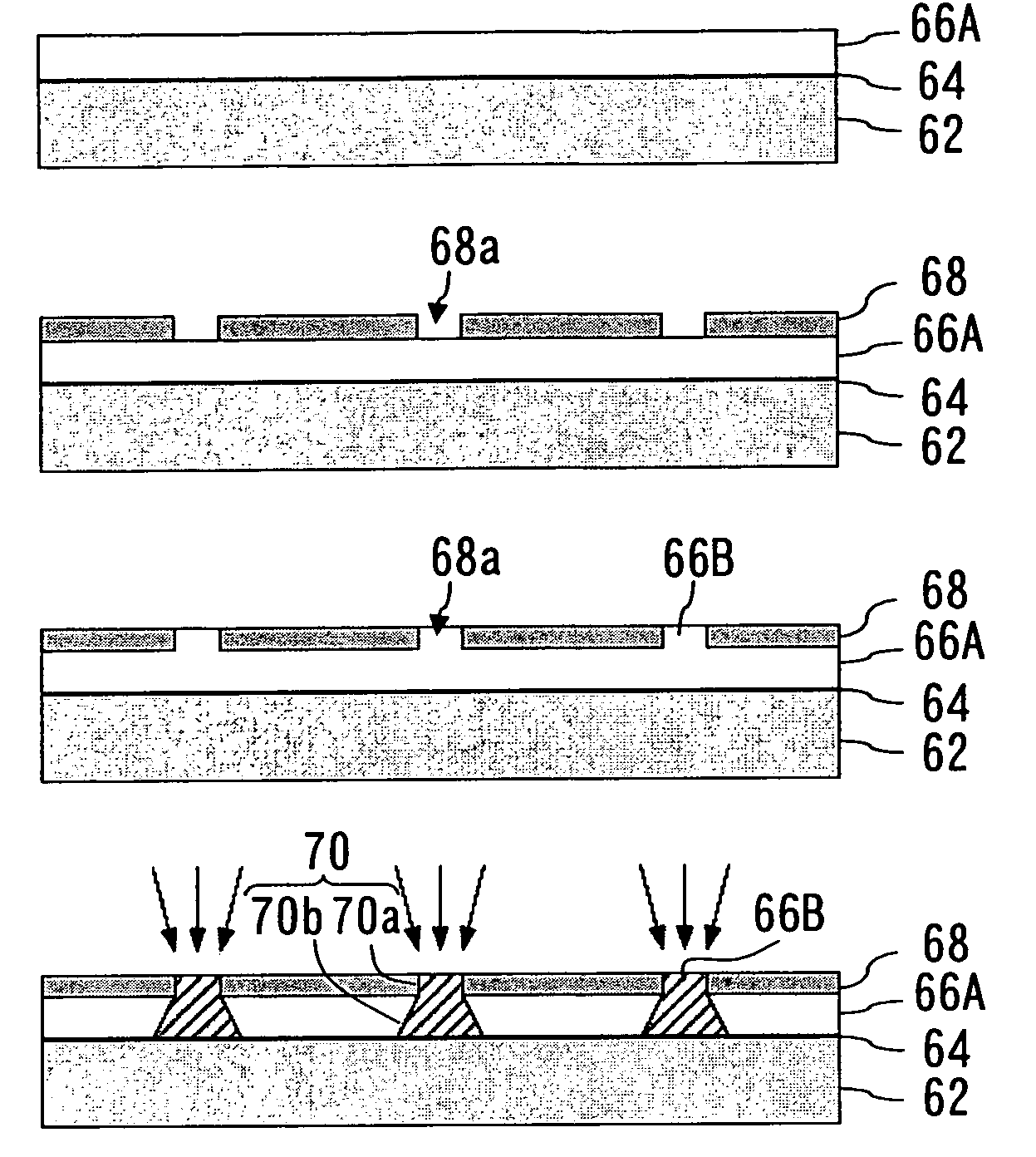
[0065]FIGS. 4A to 4G are illustrative diagrams showing a method of manufacturing a nozzle plate 60 according to a first embodiment.

[0066]Firstly, as shown in FIG. 4A, a negative resist 66A (nega-type resist: first photosensitive material) is applied onto the conductive film 64 (electrode for electroforming) formed on a matrix 62 (substrate), and the negative resist 66A is pre-baked. Instead of disposing the conductive film 64 on the matrix 62, it is possible to compose the matrix 62 from a conducting material, such as stainless steel. In the present embodiment, a resist 66A in liquid form is used, but it is also possible to use a resist in the form of a film. Next, as shown in FIG. 4B, a straight section forming member 68 is attached onto the resist 66A. The straight section forming member 68 has hole sections 68a which correspond to the straight sections of the nozzles 51. By previously fabricating a straight section forming member 68 by electroforming, it is possible to reuse the ...

second embodiment

[0071]FIGS. 7A to 7C are illustrative diagrams showing a method of manufacturing a nozzle plate 60 according to a second embodiment.

[0072]Firstly, as shown in FIG. 7A, a negative resist 66A is applied onto a conductive film (electrode for electroforming) 64 formed on a matrix 62. Here, in contrast to the first embodiment, pre-baking is not carried out, and the resist 66A is in a liquid state. Next, as shown in FIG. 7B, the straight section forming member 68 is attached onto the resist 66A, and as shown in FIG. 7C, pressure is applied to the straight section forming member 68 and resist 66A is filled into the hole sections 68a of the straight section forming member 68. Thereupon, pre-baking to the resist is carried out. The subsequent processes are the same as the corresponding steps of the first embodiment (see FIGS. 4D to 4G), and hence description thereof is omitted here.

[0073]In the second embodiment, since the straight section forming member 68 is required to be placed on the re...

third embodiment

[0074]FIGS. 8A and 8B are illustrative diagrams showing a method of manufacturing a nozzle plate 60 according to a third embodiment.

[0075]As shown in FIG. 8A, after forming exposure resist sections 70 having a tapered and straight shape on the side of a conductive film 64 disposed on a matrix 62, a metal layer 72 is formed by electroforming. The corresponding steps of the first embodiment are the same as the steps up to this process of the present embodiment (see FIGS. 4A to 4F). Thereupon, as shown in FIG. 8B, eutectoid plating of Ni and PTFE is performed on the surface of the metal layer 72, thereby creating a liquid repellent film 80 on the surface of the metal layer 72. Subsequently, the metal layer 72 including the liquid repellent film 80 is peeled away from the exposure resist sections 70 and the matrix 62 (including the conductive film 64), thereby completing the nozzle plate 60. By forming the liquid repellent film 80 on the surface on the ink ejection side of the nozzle pl...


PUM

PropertyMeasurementUnit
hole diameteraaaaaaaaaa
thicknessaaaaaaaaaa

Abstract

The method manufactures a nozzle plate including a nozzle having a tapered section where a diameter gradually decreases from a liquid supply side toward a liquid ejection side, and a straight section which is substantially cylindrical and is situated nearer a liquid ejection side of the tapered section. The method comprises the steps of: forming a first photosensitive material in a form of a layer on a substrate; placing a straight section forming member including a hole section having a shape substantially corresponding to a shape of the straight section, on the first photosensitive material; filling a second photosensitive material into the hole section; radiating a prescribed light toward the straight section forming member, in such a manner that substantially all of the second photosensitive material is exposed and the first photosensitive material is exposed in a tapered shape having a diameter which gradually increases toward the substrate; removing the straight section forming member from the first photosensitive material and the second photosensitive material; carrying out development of the first photosensitive material and the second photosensitive material after removing the straight section forming member from the first photosensitive material and the second photosensitive material; forming a metal layer which is to serve as the nozzle plate, on the substrate, by a plating method where the first photosensitive material and the second photosensitive material left on the substrate after carrying out the development of the first photosensitive material and the second photosensitive material are used as a mold; and removing the metal layer from the substrate, the first photosensitive material and the second photosensitive material.

Description

BACKGROUND OF THE INVENTION[0001]1. Field of the Invention[0002]The present invention relates to a method of manufacturing a nozzle plate, and more particularly, to a method of manufacturing a nozzle plate having a nozzle of a cross-sectional shape which is formed by combining a tapered section and a straight section.[0003]2. Description of the Related Art[0004]An inkjet recording apparatus (inkjet printer) is known which forms a desired image on a recording medium by ejecting ink droplets from nozzles toward a recording medium, while causing a print head including a nozzle plate having a plurality of nozzles on an ejection surface opposing the recording medium to move relatively with respect to the recording medium.[0005]In a print head of this kind, if dimensional accuracy is poor in terms of the shape and position of the nozzles formed in the nozzle plate, or the like, then variations occur in the size (volume) of the ink droplets, their direction of flight and their speed of fli...

Claims


Application Information

Patent Timeline
Patent Type & Authority Patents(United States)
IPC IPC(8): B41J2/16
CPCB41J2/14233B41J2/1606B41J2/162B41J2/1625B41J2/1631G03F7/0015G03F7/201G03F7/2014B41J2/1643Y10T29/49401B41J2002/14459G03F7/16
Inventor YOKOUCHI, TSUTOMU
Owner FUJIFILM CORP
Why Eureka
Try Eureka