
Step-down in-line butt connector

Inactive Publication Date: 2007-08-14
ENDACOTT JOHN E
View PDF30 Cites 43 Cited by
  • Summary
  • Abstract
  • Description
  • Claims
  • Application Information

AI Technical Summary

Benefits of technology

[0008]The step-down in-line butt connector of the present invention addresses the aforementioned needs in the art by providing a butt connector that can receive a pair of wires in-line (or a trio of wires with two wires at one end and one at the other) wherein the wires are of different gauge and wherein each end of the butt connector is sized to appropriately receive the disparate sized wires in order to be able to crimp upon the wire with a normal setting of the crimping tool. The in-line butt connector is of relatively simple design and construction and is relatively easy to use.

Problems solved by technology

The problem with this system is that while the end that receives the smaller gauged wire produces a proper crimp, the end that receives the larger gauged wire does not always produce a satisfactory crimp.
The crimping process may not adequately impact onto this smaller gauged wire resulting in a less than ideal electrical connection and a mechanical connection that is more prone to fail as this smaller wire may have a higher tendency to come loose from its crimped butt connector.
However, the problem with this system lies in the fact that in such butt connectors the outside diameter of the butt connector is constant.
However, in reality, such is not the case and the crimper tool is not reset between crimps between one end and the other.
As such, either insufficient crimp pressure is applied at the thick walled end of the butt connector due to the crimping tool being set to crimp at a pressure at the thin walled end of the butt connector, or too much crimp pressure is applied at the thin walled end of the butt connector due to the crimping tool being set at a pressure to crimp at the thin walled end.
In either case, the result is a crimp that is less than satisfactory.

Method used


Image

  • Step-down in-line butt connector
  • Step-down in-line butt connector
  • Step-down in-line butt connector

Examples


Embodiment Construction

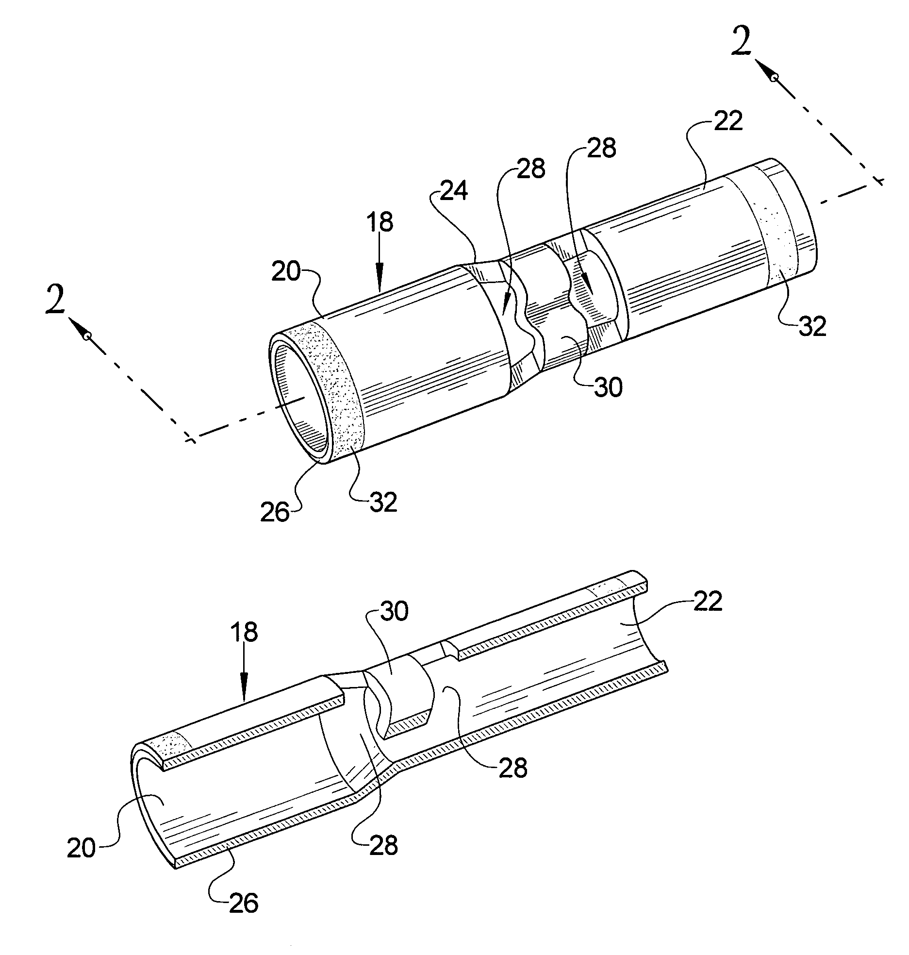
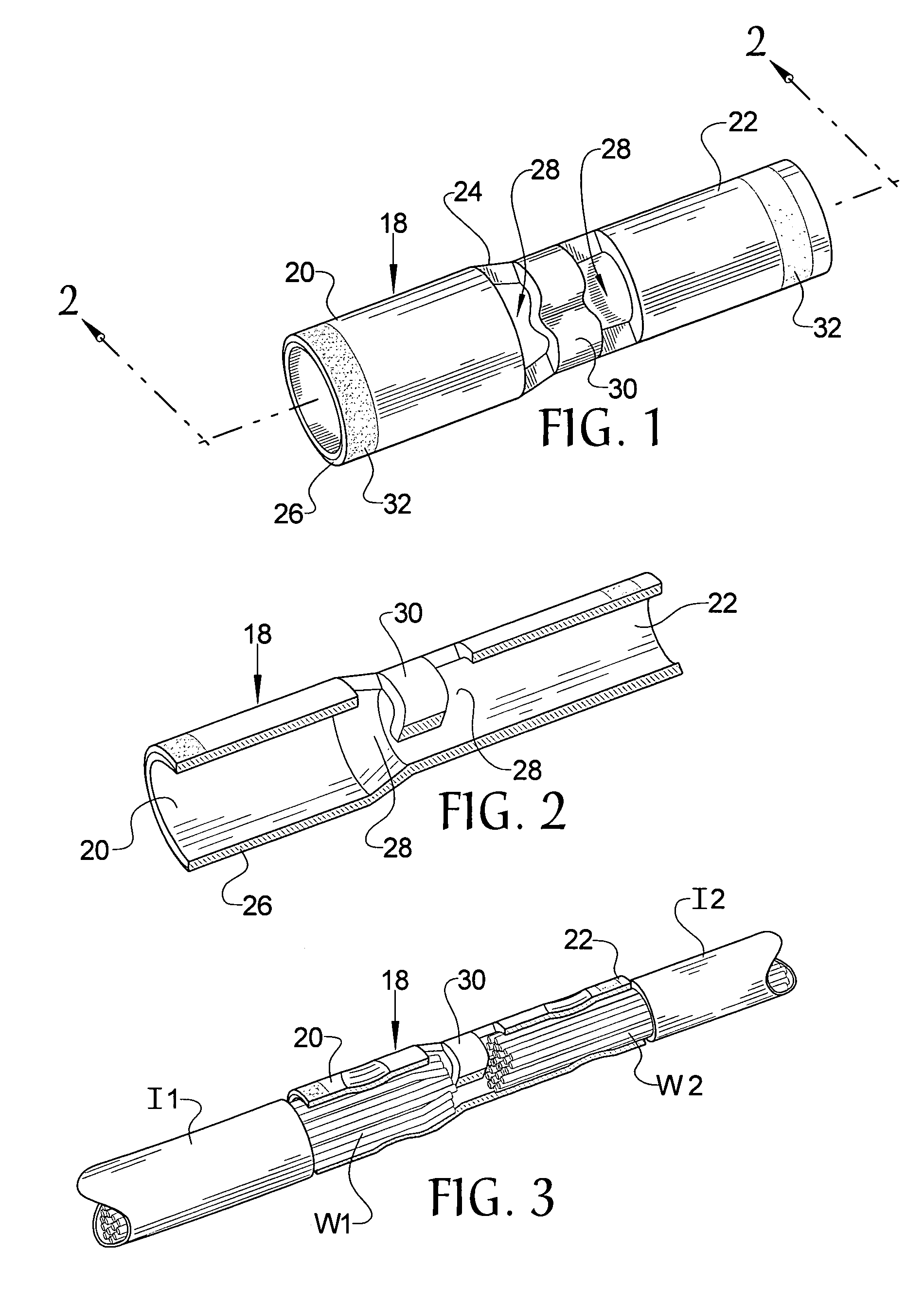
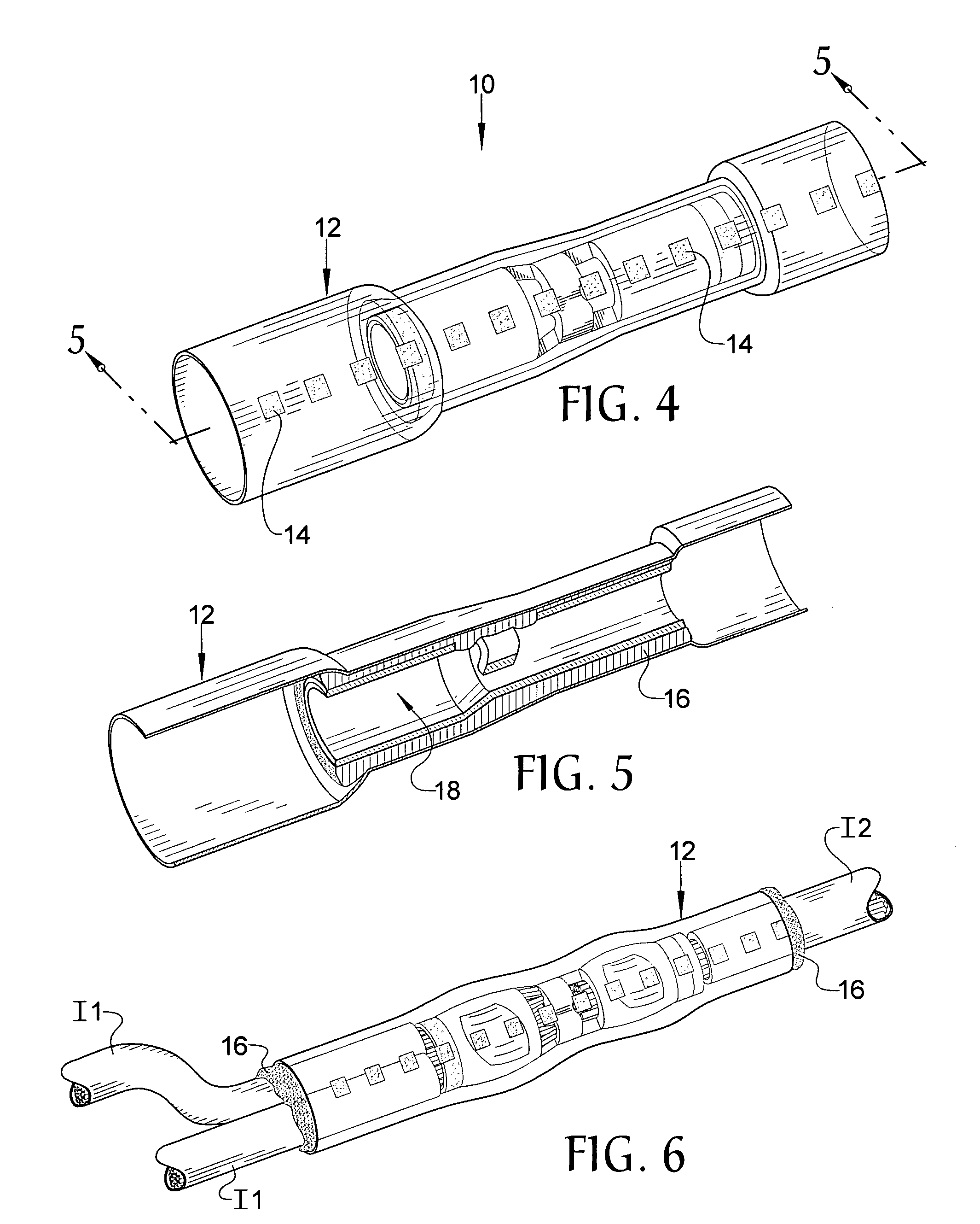
[0017]Referring now to the drawings, it is seen that the step-down in-line butt connector of the present invention, generally denoted by reference numeral 10, is comprised of a heat shrinkable hollow sleeve 12. The hollow sleeve is at least partially translucent for viewing thereinto and may be tinted, the specific tint corresponding to a specific size to be used for a specific size of body member discussed below, and may have certain identification indicia 14 printed thereon to allow a user to visually determine the size of the hollow sleeve 12. The hollow sleeve 12 may be made from a heat shrinkable material, such as polyolefin, and, advantageously, has a heat shrink ratio at least about 4 to 1, although ratios that are less may also be used. As seen, the medial portion of the hollow sleeve 12 is initially at least partially heat shrunk. An adhesive element 16 is located within the hollow sleeve 12, the adhesive element 16 being co-extruded with the hollow sleeve 12, and the adhes...


PUM


Abstract

A step-down in-line butt connector receives a pair of wires, one at either end, wherein the wires are each of a different gauge. A hollow tubular body member has a first end and a second end such that the inside diameter and the outside diameter of the first end is larger relatively to the inside diameter and the outside diameter of the second end respectively, while the wall thickness of the body member remains relatively constant between the first end and the second end. An opening is located medially of the body member and may have a stop thereat. The body member is received within a heat shrinkable hollow sleeve that is heated after each end of the body member is crimped in order for the sleeve to form around the body member. A heat activated adhesive within the hollow sleeve helps seal the overall system.

Description

BACKGROUND OF THE INVENTION[0001]1. Field of the Invention[0002]The present invention relates to an in-line butt connector that receives a pair of wires, one on each end of the connector, wherein the wires are of a different gauge and crimped thereat and wherein each end of the butt connector is of a different size in order to accommodate the disparate sized wires.[0003]2. Background of the Prior Art[0004]In-line butt connectors are designed to receive a pair of wires in an end to end relationship and to mechanically and electrically connect these wires. The butt connector receives a wire at each end of the connector and thereafter the butt connector is crimped in order to secure each wire and facilitate the mechanical and electrical connection of the wires. In addition, some butt connectors may have solder and / or a heat shrinkable sleeve to further aid in wire connection and to protect the connection from exposure to the elements. Generally, but not always, each of the wires receiv...

Claims


Application Information

Patent Timeline
IPC IPC(8): H01R4/00
CPCH01R4/183H01R4/20H01R11/07H01R4/726
Inventor ENDACOTT, JOHN E.
Owner ENDACOTT JOHN E
Learn More