LED control circuit

Active Publication Date: 2007-08-14
SEMICON COMPONENTS IND LLC
View PDF4 Cites 15 Cited by
  • Summary
  • Abstract
  • Description
  • Claims
  • Application Information

AI Technical Summary

Benefits of technology

[0017]In consideration of the above, the present invention advantageously provides an LED control circuit for controlling a plurality of LEDs with different emission colors comprising, with respect to each of the plurality of LEDs, a counter which increments or decrements a count value at a predetermined clock in response to a count start signal externally supplied; a signal conversion circuit which converts the count value in the counter into an analog signal displaying intensity corresponding to the count value and outputs the analog signal as an output signal; a signal generation circuit which generates, based on the output signal from the signal conversion circuit and brightness data externally specified to corresponding one of the plurality of LEDs, an analog signal displaying intensity corresponding to a product of the output signal and the corresponding brightness data, and outputs the generated analog signal; and a driving circuit for driving corresponding one of the plurality of LEDs according to the analog signal output from the signal generation circuit, to thereby gradually and simultaneously modulate brightness levels of the plurality of LEDs according to the count value.
[0018]According to a further aspect, the present invention also provides an LED control circuit for controlling a plurality of LEDs with different emission colors comprising, with respect to each of the plurality of LEDs, a counter which increments or decrements a count value at a predetermined clock in response to a count start signal externally supplied; a signal conversion circuit which converts brightness data externally specified to corresponding one of the plurality of LEDs into an analog signal displaying intensity corresponding to the brightness data and then outputs the analog signal as an output signal; a signal generation circuit which generates, based on the output signal from the signal conversion circuit and the count value provided from the counter, an analog signal displaying intensity corresponding to a product of the corresponding output signal and the count value, and outputs the generated analog signal, and a driving circuit for driving corresponding one of the plurality of LEDs according to the analog signal output from the signal generation circuit, to thereby gradually and simultaneously modulate the brightness levels of the plurality of LEDs according to the count value.

Problems solved by technology

Further, when fade-outs are simultaneously started, for example, the LED 1g reaches the turned off state (a condition where the duty factor is zero) ahead of the LED 1r, which results in a situation that only the LED 1r thereafter remains turned on.

Method used


Image

  • LED control circuit
  • LED control circuit
  • LED control circuit

Examples


embodiment 1

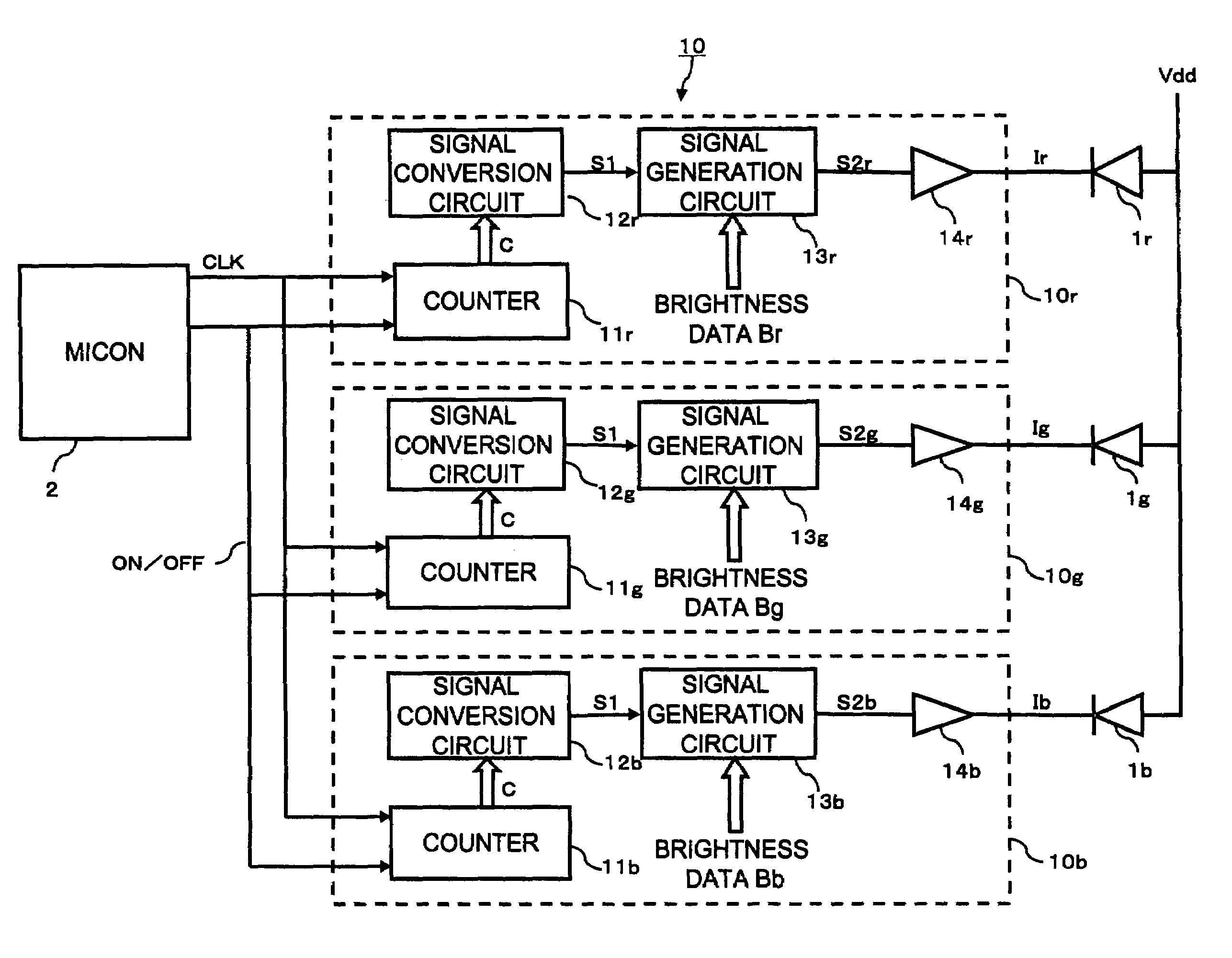
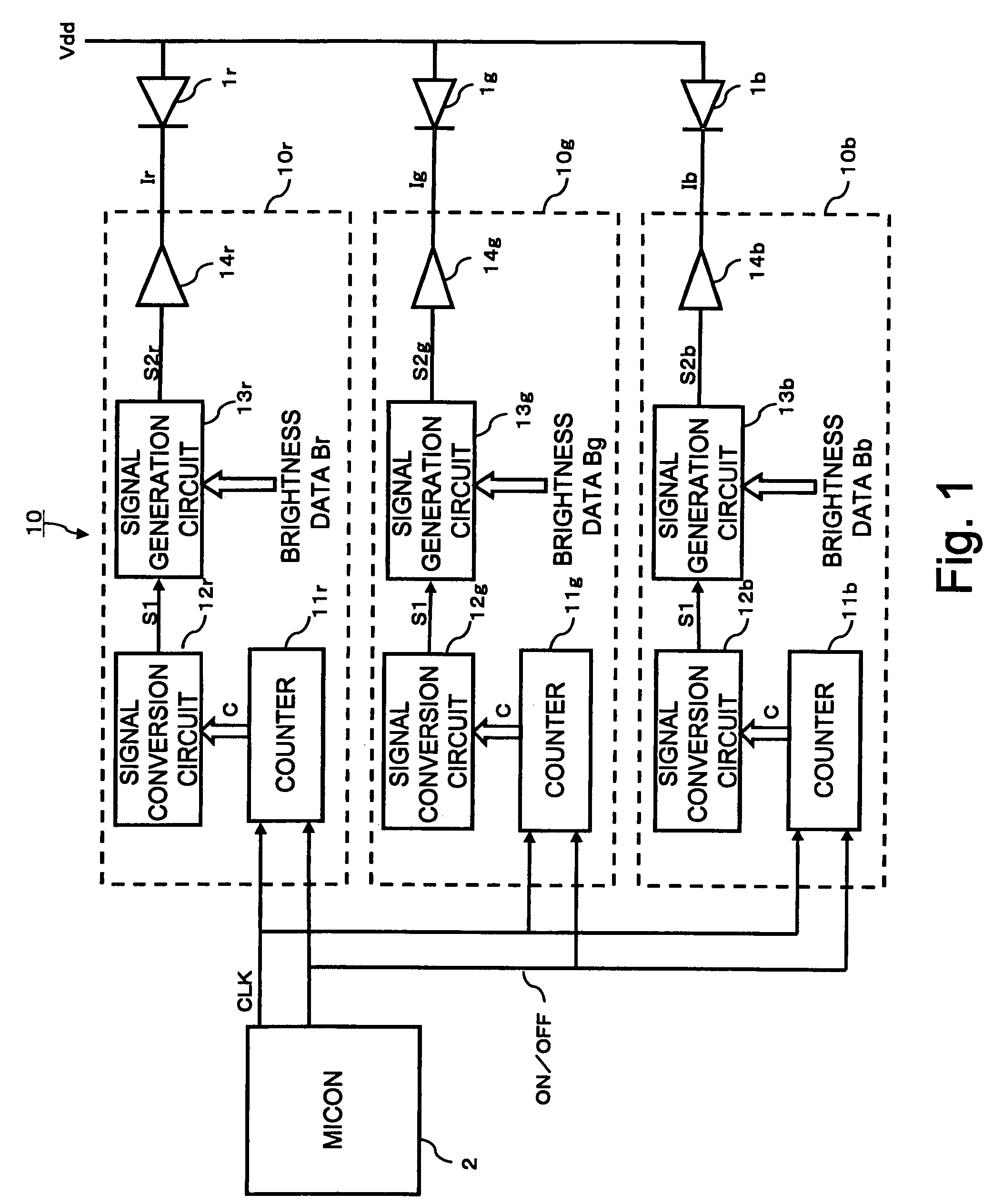
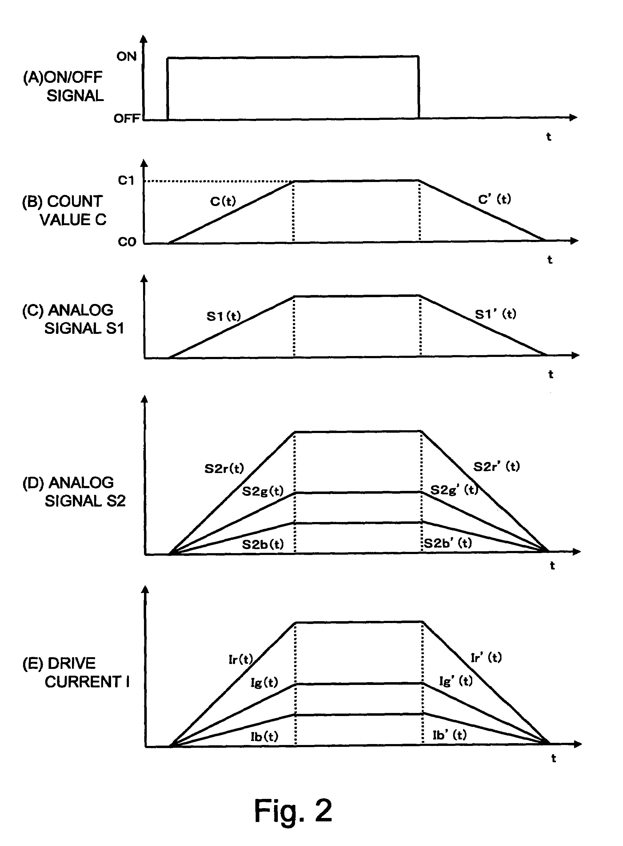
[0035]FIG. 1 is a circuit block diagram showing a configuration of an LED control circuit 10 according to a first embodiment of the present invention. The LED control circuit 10 is incorporated in a cellular phone or a PHS to control turning on and off of three color LEDs in response to receipt of an incoming call and a text message. In particular, the LED control circuit 10 is designed to realize a fade-in and a fade-out of halftone color light. Here, the fade-in means that an LED becomes gradually brighter from a turned-off state to a predetermined lighting state, while the fade-out means that the LED becomes gradually darker from the lighting state to the turned-off state.

[0036]In FIG. 1, the input terminal of the LED control circuit 10 is connected to a microcomputer (micon) 2, while its output terminals are connected to a red LED 1r, green LED 1g, and blue LED 1b. The LED control circuit 10 comprises an RLED control circuit 10r for controlling the LED 1r, GLED control circuit 1...

configuration example 1

[0057]FIG. 3 is a circuit block diagram of the RLED control circuit 10r according to Configuration Example 1. In this example, the signal conversion circuit 12r and the signal generation circuit 13r are both configured as a DA conversion circuit for converting an input digital signal into an analog current signal.

[0058]Upon receipt of the count value C from the counter 11r, the signal conversion circuit 12r multiplies a reference current Iref by the count value C and outputs a current C·Iref as the analog signal S1.

[0059]The signal generation circuit 13r converts the brightness data Br into an analog current signal using the current C·Iref supplied from the signal conversion circuit 12r as a reference current for DA conversion. Specifically, the signal generation circuit 13r multiplies the reference current C·Iref by the brightness data Br and outputs the resultant current Br·C·Iref as the analog signal S2r.

configuration example 2

[0060]FIG. 4 is a circuit block diagram of an RLED control circuit 10r according to Configuration Example 2. In this example, the signal conversion circuit 12r is a DA conversion circuit for converting an input digital signal into an analog current signal, and the signal generation circuit 13r is a PWM circuit for converting an input digital signal into a PWM signal.

[0061]Upon receipt of the count value C from the counter 11, the signal conversion circuit 12r multiplies the reference current Iref by the count value C and outputs the resultant current C·Iref as the analog signal S1.

[0062]The signal generation circuit 13r converts the brightness data Br (4-bit data, 0˜15 in decimal form) into a PWM signal using the current C·Iref supplied from the signal conversion circuit 12r as a reference current for PWM. Specifically, the signal generation circuit 13r outputs a pulse current having a current amplitude of C·Iref and a duty factor of Br / 15 as the analog signal S2r. Here, it should b...


PUM


Abstract

An LED control circuit for controlling a plurality of LEDs with different emission colors comprises a counter which increments or decrements a count value at a predetermined clock in response to a count start signal externally supplied, a signal conversion circuit which converts the count value into an analog signal displaying intensity corresponding to the count value and outputs the analog signal as an output signal, a signal generation circuit which generates, based on the output signal from the signal conversion circuit and brightness data externally specified to its corresponding LED, an analog signal displaying intensity corresponding to a product of the output signal and the brightness data, and a driving circuit which drives its corresponding LED according to the analog signal output from the signal generation circuit, to gradually and simultaneously change the brightness of the LEDs in accordance with the count value.

Description

[0001]The entire disclosure of Japanese Patent Application No. 2004-234070, including the specification, claims, drawings, and abstract, is incorporated herein by reference.BACKGROUND OF THE INVENTION[0002]1. Field of the Invention[0003]The present invention relates to an LED control circuit for controlling a plurality of LEDs with different emission colors, and in particular to controlling the brightness of an LED.[0004]2. Description of the Related Art[0005]By using a combination of red (R), green (G), and blue (B) LEDs, i.e. three primary color LEDs, and adjusting the brightness of the LEDs, various emission colors can be produced. Such three color LEDs are incorporated in, for example, cellular and PHS mobile phones. In a cellular phone, for example, upon receipt of an incoming call or a text massage, a corresponding color light is emitted to notify a user of the receipt. As a method of realizing multicolor multi-gradation display using three color LEDs, there has been known a P...

Claims


Application Information

Patent Timeline
Patent Type & Authority Patents(United States)
IPC IPC(8): G01G3/10G01G5/02H05B37/02H01L33/00
CPCH05B33/0842H05B33/086H05B33/0863H05B45/20H05B45/00H05B45/397H05B45/325Y02B20/30G09G3/32G09G3/20
Inventor ISHII, TAKAAKIOHTAKA, NOBUYUKI
Owner SEMICON COMPONENTS IND LLC
Why Eureka
Try Eureka