Bounding box signal detector

a detector and box technology, applied in the field of electronic test equipment, can solve the problems of not having a good equipment, not having a good detector, and being economically impractical to use an expensive data acquisition techniqu

Inactive Publication Date: 2007-08-14
AGILENT TECH INC
View PDF2 Cites 16 Cited by
  • Summary
  • Abstract
  • Description
  • Claims
  • Application Information

AI Technical Summary

Problems solved by technology

These types of applications generally require a high speed ADC (Analog to Digital Converter), and are typically very expensive to implement.
It is economically impractical to use an expensive data acquisition technique that might be justifiable for two or four channels in a digital oscilloscope for all sixty-four or one hundred twenty-eight channels of an EDA.
So far, nobody's equipment is quite that good, but the notion of “better is worse” is a disgusting situation that motivates the improvements described in connection with FIGS. 3 and 4.

Method used


Image

  • Bounding box signal detector
  • Bounding box signal detector
  • Bounding box signal detector

Examples


Embodiment Construction

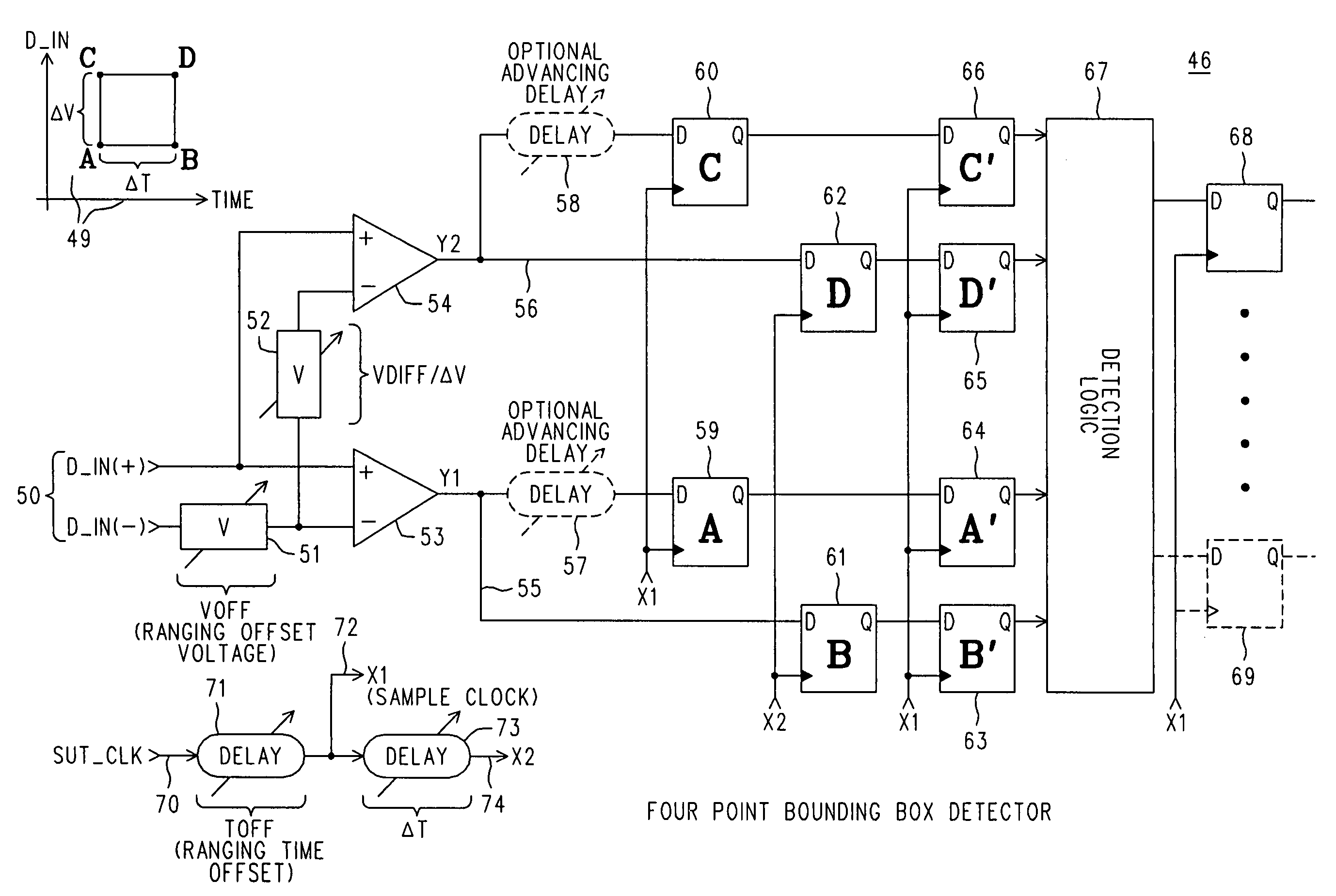
[0023]We turn now to FIG. 5, wherein is depicted a simplified block diagram 46 of what we shall term a four point BOUNDING BOX DETECTOR. Diagram 49 in the upper left-hand corner of the figure illustrates, in general, one kind of four point BOUNDING BOX, which in this case is defined by the four vertices labeled A, B, C and D. Each vertex represents a particular combination of a threshold being met at a certain time. So, A and B have the same threshold voltage (which will be VOFF in this case), but are ΔT apart in time.

[0024]A signal X1 (72) is produced by a VARIABLE DELAY 71 applied to SUT_CLK 70, and is delayed from SUT_CLK by a ranging time offset we term TOFF. X1 is the start of a time interval we call ΔT and that is delimited by another signal X2 (74). X2 is produced from X1 by another VARIABLE DELAY 73. It will be appreciated that the VARIABLE DELAY circuits can be, for example, a tapped series of buffers.

[0025]We can see how this works by noticing that the input signal 50, whi...


PUM


Abstract

A description of signal behavior in the vicinity of a time and voltage of interest is produced by defining a region in the (time, voltage) plane that is a closed straight sided figure whose vertices are identified by threshold crossings offset for the voltage of interest and clocked by time delays offset from a clock time of interest. A first set of latches clocked by the time delays accumulates the state of signal behavior relative to the threshold voltages as it occurs, and their contents are subsequently transferred to a second set of latches at the start of a new clock cycle, allowing a new accumulation to begin and also allowing a detection logic circuit to operate on a unified and completed collection of indicators of what the just concluded description amounts to. The detection logic circuit responds to the combinations of latched indications to produce a signal corresponding to that description. The closed figure need not be a rectangle, and it may also serve as an indication that a signal went into a region that it should not have, e.g., an eye violation detector.

Description

BACKGROUND OF THE INVENTION[0001]There are many types of electronic test equipment whose operation includes the digital acquisition of a series of analog voltage values. In some cases, such as in real time digital oscillography, an acquisition record is required for a large number of consecutive samples taken in rapid succession. These types of applications generally require a high speed ADC (Analog to Digital Converter), and are typically very expensive to implement. There are other kinds of related applications where a significantly lower cost is desired, which can be achieved if certain performance requirements can be relaxed. These other applications often take advantage of an expected periodicity wherein the signal's previous behavior is repeated, and given enough time a complete description of the signal can be created by sampling different locations within that behavior during successive instances of the behavior. This can remove the need for sustained high speed operation fr...

Claims


Application Information

Patent Timeline
Patent Type & Authority Patents(United States)
IPC IPC(8): H03D1/00G01R13/00G01R13/34G01R31/319G01R31/3193H03K5/08
CPCG01R31/31922G01R31/31937H03K5/08
Inventor WOOD, GLENNESKELDSON, DAVID D.
Owner AGILENT TECH INC
Why Eureka
Try Eureka