
Multichannel synchronous output calibrating apparatus and method

A calibration device and multi-channel technology, applied in the direction of pulse processing, analog conversion, electrical components, etc., can solve the problems of poor channel consistency and uncorrectable errors, and achieve the effects of low cost, reduced pulse width measurement error, and high precision

Active Publication Date: 2018-03-30
THE 41ST INST OF CHINA ELECTRONICS TECH GRP
View PDF7 Cites 37 Cited by
  • Summary
  • Abstract
  • Description
  • Claims
  • Application Information

AI Technical Summary

Problems solved by technology

At the same time, during error correction, the internal calibration module only adjusts the phase of the waveform, and cannot correct the error caused by the delay of the sampling clock, resulting in poor channel consistency.

Method used


Image

  • Multichannel synchronous output calibrating apparatus and method
  • Multichannel synchronous output calibrating apparatus and method
  • Multichannel synchronous output calibrating apparatus and method

Examples


Embodiment Construction

[0061] Below in conjunction with accompanying drawing and specific embodiment the present invention is described in further detail:

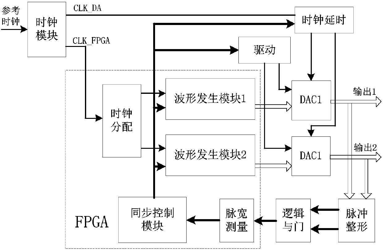
[0062] combine figure 1 As shown, a multi-channel synchronous output calibration device includes a clock module, a clock delay module, a waveform generation module, a pulse shaping module, a logic AND gate module, a pulse width measurement module and a synchronization control module.

[0063] Among them, the direction of the signal flow in each of the above hardware modules is:

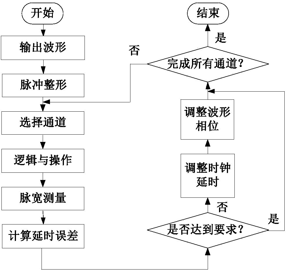
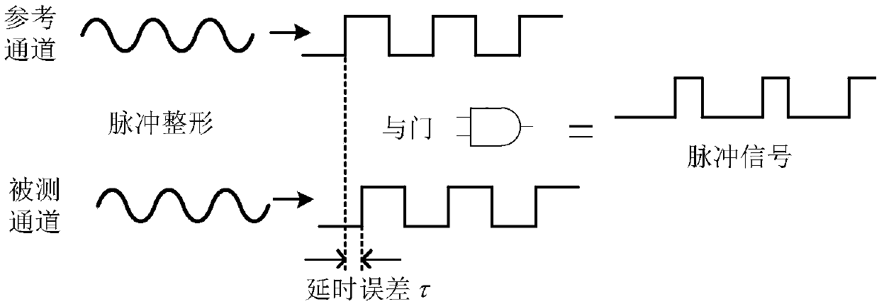
[0064] The sine wave signal output by each channel is input to the pulse shaping module for pulse shaping to obtain a square wave signal;

[0065] A reference channel is specified, and other channels are sequentially ANDed with the square wave signal of the reference channel in the logic AND gate module to obtain a pulse signal;

[0066] The pulse width measurement module calculates the delay error between channels by measuring the pulse width of the pulse signal;

...


PUM


Abstract

The invention discloses a multichannel synchronous output calibrating apparatus and method. The calibrating apparatus includes a clock module, a clock time delay module, a waveform generation module,a pulse shaping module, a logic AND gate module, a pulse width measurement module and a synchronous control module, wherein an inter-channel synchronous time delay error is obtained by adopting the pulse shaping module, the logic AND gate module and the pulse width measurement module. The circuit structure is simple, the hardware implementation is easy, the complex calculation is avoided, an ADC circuit and a high-performance calculation module do not need and the cost is low; when the error is corrected, the calibrating apparatus adjusts a time delay and a waveform phase of a sampling block sequentially via the clock time delay module and the waveform generation module until the inter-channel synchronous time delay error reaches to a designed requirement, so the precision is high and thechannel consistency is good; and in additional, since a cooperative manner of precise time delay adjustment and edge inspection is adopted by the pulse width measurement module, a pulse width measurement error is effectively reduced.

Description

technical field [0001] The invention belongs to the field of arbitrary waveform generation, in particular to a multi-channel synchronous output calibration device and method. Background technique [0002] Arbitrary waveform generator is a signal generation source based on digital, analog and computer technology. It can provide some conventional function waveforms, complex editable waveforms, environmental analog signals, digital modulation signals, etc. It is widely used in radar, communication, biological Various fields such as medical treatment and chip detection. Usually, arbitrary waveform generators integrate multiple output channels to meet the needs of users for multiple waveform signals, and have powerful signal excitation capabilities, including high-speed waveform generators, function generators, pulse / sequence generators, sweep frequency generator, trigger generator, broadband white noise signal generator and amplitude modulation source, etc. At the same time, t...

Claims


Application Information

Patent Timeline
IPC IPC(8): H03M3/00H03K19/20H03K5/135H03K5/133
CPCH03K5/133H03K5/135H03K19/20H03M3/38
Inventor 逄锦昊刘宇吴恒奎滕友伟钱红梅
Owner THE 41ST INST OF CHINA ELECTRONICS TECH GRP
Learn More