
Toner supply device

a technology of toner supply and auxiliary components, which is applied in the direction of liquid transfer devices, movable measuring chambers, instruments, etc., can solve the problems of increasing the cost of one sheet, increasing the burden on the environment, and difficulty in reducing the size of the developing unit, etc., and achieves the effect of restrainting toner and simple structur

Inactive Publication Date: 2007-08-14
KYOCERA DOCUMENT SOLUTIONS INC
View PDF11 Cites 14 Cited by
  • Summary
  • Abstract
  • Description
  • Claims
  • Application Information

AI Technical Summary

Benefits of technology

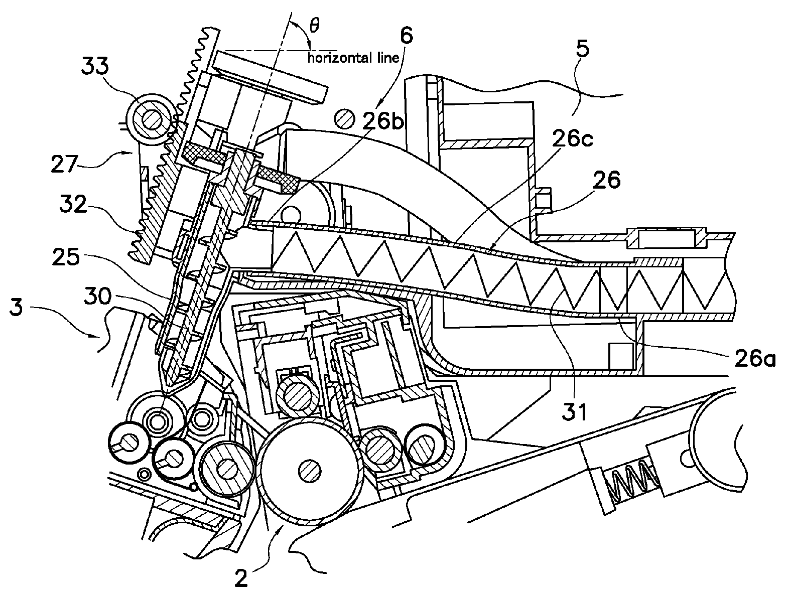
[0016]Although the toner is supplied downward to the developing device within the supply pipe, the remainder of the toner within the toner pipe is restrained because the supply pipe is located such that the center axis of the supply pipe is slanted relative to the horizontal line at a repose angle of the toner or more. Consequently, the remaining toner is prevented from contaminating inside of the device when the supply pipes are pulled out from the developing device.
[0042]In addition, the present invention, the amount of the toner supply from the toner container to the image forming unit is precisely managed.

Problems solved by technology

As a result, it is difficult to reduce the developing unit in size.
Although it is possible to set a printing capability of toner to 4,000 sheets or under, the cost per one sheet increases in that case.
In addition, when the toner is completely consumed, it is necessary to replace the developing units each time.
As a result, it increases the burden on the environment.
Furthermore, in the conventional device, it is difficult to precisely manage the amount of the toner supply when the toner is supplied from the toner container to the developing unit, because the toner in the toner container is supplied to the developing device by free fall.

Method used


Image

  • Toner supply device
  • Toner supply device
  • Toner supply device

Examples


Embodiment Construction

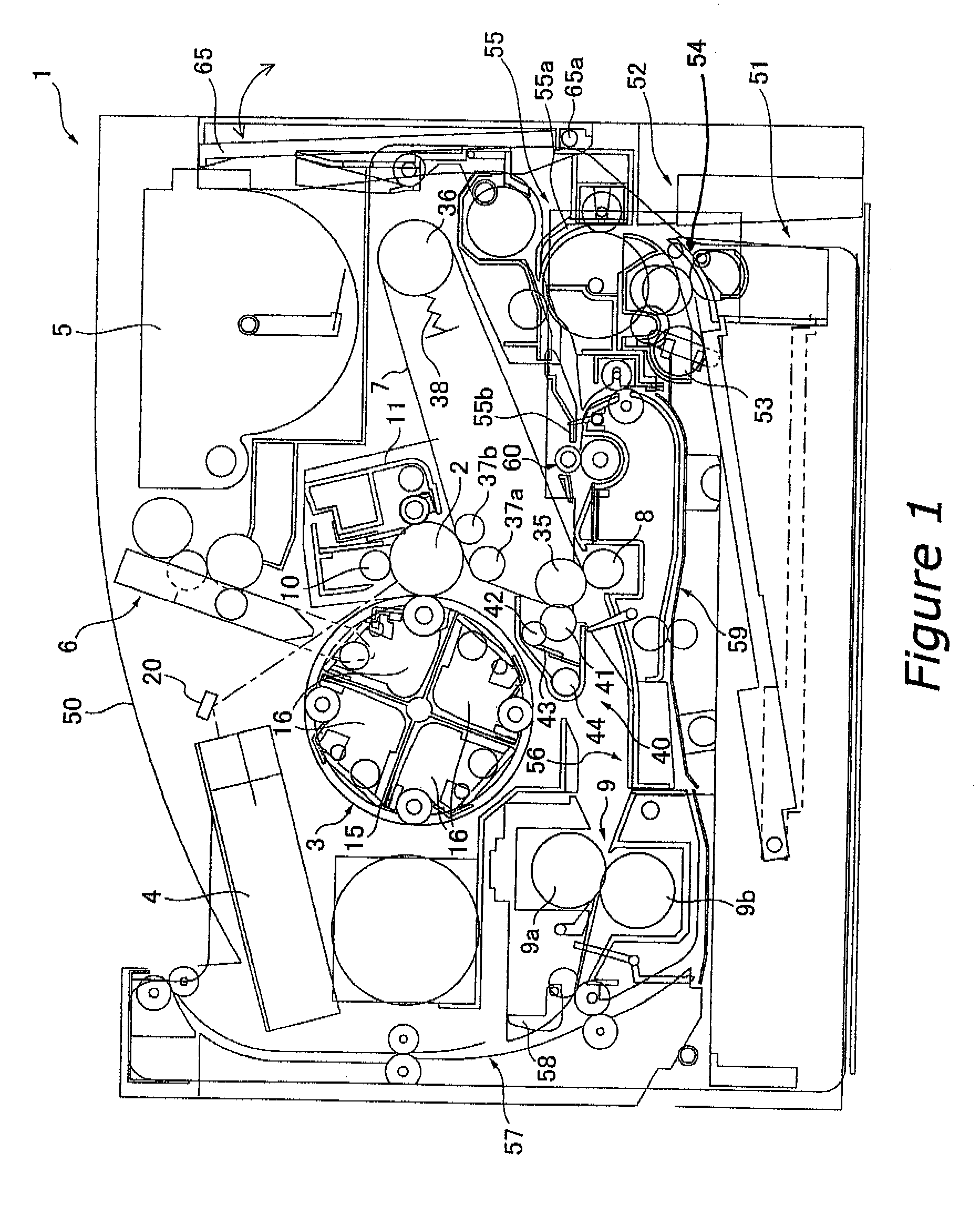
[0051]FIG. 1 shows a color printer 1 as a color image forming device according to one embodiment of the present invention. FIG. 1 is a view showing a frame format of locations of each of the components, and thus the details of each of portions are omitted.

[0052]Overall Structure

[0053]The color printer 1 is connected to a computer, for example, and is capable of printing a color image on a sheet in accordance with image data sent from the computer. In this color printer 1, the right side of FIG. 1 is the side from which an operator operates the color printer 1. In the below description, the right side in FIG. 1 is referred to as the “front side” and the left side in FIG. 1 is referred to as the “rear side”.

[0054]The color printer 1 includes a photosensitive drum 2, a rotary developing device 3, a laser unit 4, a toner container 5, a toner supply device 6, an intermediate transfer belt 7, a secondary transfer roller 8, and a fixing device 9. In this device, the photosensitive drum 2, ...


PUM


Abstract

A toner supply device is disclosed that supplies toner contained in a toner container to a developing device in an image forming device. The toner supply device includes a conveyance pipe for conveying the toner from the toner container to the developing device downward, and at least one supply pipe for supplying the toner from the conveyance pipe to the developing device downward. The conveyance pipe is connected to the toner container for conveying the toner from the toner container to the developing device. The supply pipe has an upper portion connected to the conveyance pipe and a lower end capable of advancing into the developing device. In addition, a conveyance member is rotatably located in the supply pipe for conveying the toner downward. The supply pipe is located such that a center axis of the supply pipe is slanted relative to the horizontal line at a repose angle of the toner or more.

Description

BACKGROUND OF THE INVENTION[0001]1. Field of the Invention[0002]The present invention relates to a toner supply device, and more particularly to a toner supply device for supplying toner from a toner container located apart from a developing device to the developing device.[0003]2. Background Information[0004]An image forming device utilizing an electrophotographic system includes a photosensitive drum as an image bearing member and other devices located circumferentially around the drum, such as a charger, an exposure device, a developing device, a transfer device, a cleaning device, and so on. In addition, a fixing device is provided downstream of the photosensitive drum in a direction in which the transfer device extends. In this image forming device, first, a surface of the photosensitive drum is uniformly charged by the charger. Then, the photosensitive drum is exposed by the exposure device in accordance with image data so that an electrostatic latent image is formed on the ph...

Claims


Application Information

Patent Timeline
Patent Type & Authority Patents(United States)
IPC IPC(8): G03G15/00G03G15/01G03G15/08
CPCG03G15/0877G03G15/0886G03G15/0879Y10S222/01
Inventor TOMOE, TETSUROTANDA, TETSUOTANABE, KENICHI
Owner KYOCERA DOCUMENT SOLUTIONS INC
Learn More