
FEC (Forward Error Correction) decoder with dynamic parameters

a decoder and dynamic parameter technology, applied in the field of communication systems, can solve the problems of many deficiencies in the type of prior art receiver, undesirable decoding and operational latency, and inability to achieve very good operation and performan

Inactive Publication Date: 2007-08-14
AVAGO TECH WIRELESS IP SINGAPORE PTE
View PDF7 Cites 202 Cited by
  • Summary
  • Abstract
  • Description
  • Claims
  • Application Information

AI Technical Summary

Benefits of technology

This approach reduces latency and improves error correction capabilities, enabling efficient FEC decoding even at low SNR conditions by protecting parameter information within the FEC stream and allowing for adaptive parameter adjustments in real-time.

Problems solved by technology

However, the approaches for doing this within the prior art do not provide for very operation and performance.
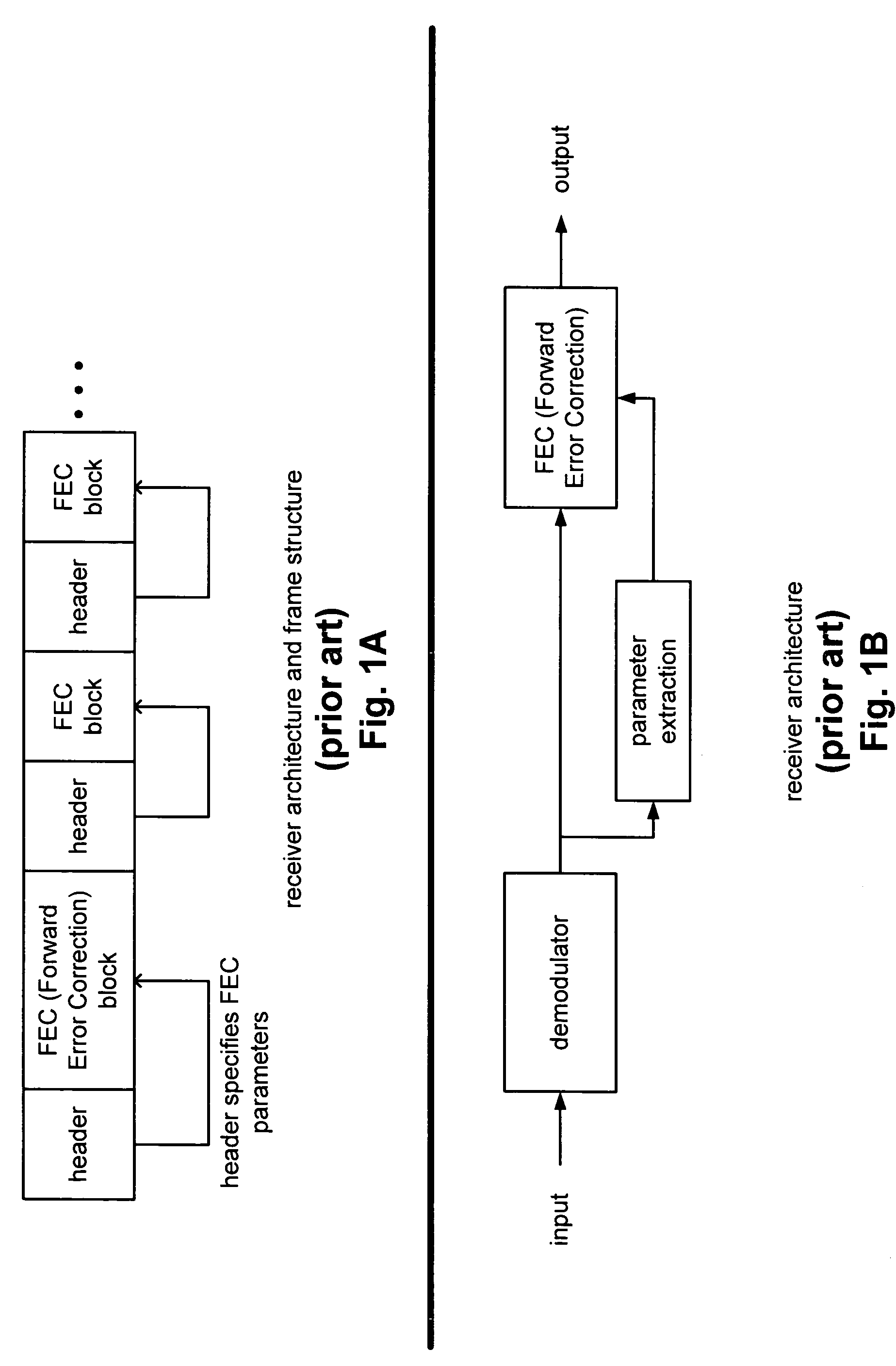
This prior art inherently involves an undesirable decoding and operational latency, in that, the header of the FEC block must be processed (to extract the information corresponding to the FEC operational parameters by which the subsequent FEC block is to be decoded), then the FEC block must be configured according to that extracted information, and then the FEC block is then actually decoded.
This type of prior art receiver suffers from many deficiencies.
For example, it cannot operate at low SNR (Signal to Noise Ratio) because the frame headers are vulnerable to noise, as they are typically not protected by any error control code.
Also, this prior art approach suffers from the inherently slow and serial approach performed by this prior art receiver architecture that includes a parameter extraction functional block that must be employed before performing any FEC decoding of the FEC blocks of the input signal stream that immediately follow the frame header (e.g., the frame header that includes the FEC decoding parameters for that immediately following FEC block).

Method used


Image

  • FEC (Forward Error Correction) decoder with dynamic parameters
  • FEC (Forward Error Correction) decoder with dynamic parameters
  • FEC (Forward Error Correction) decoder with dynamic parameters

Examples


Embodiment Construction

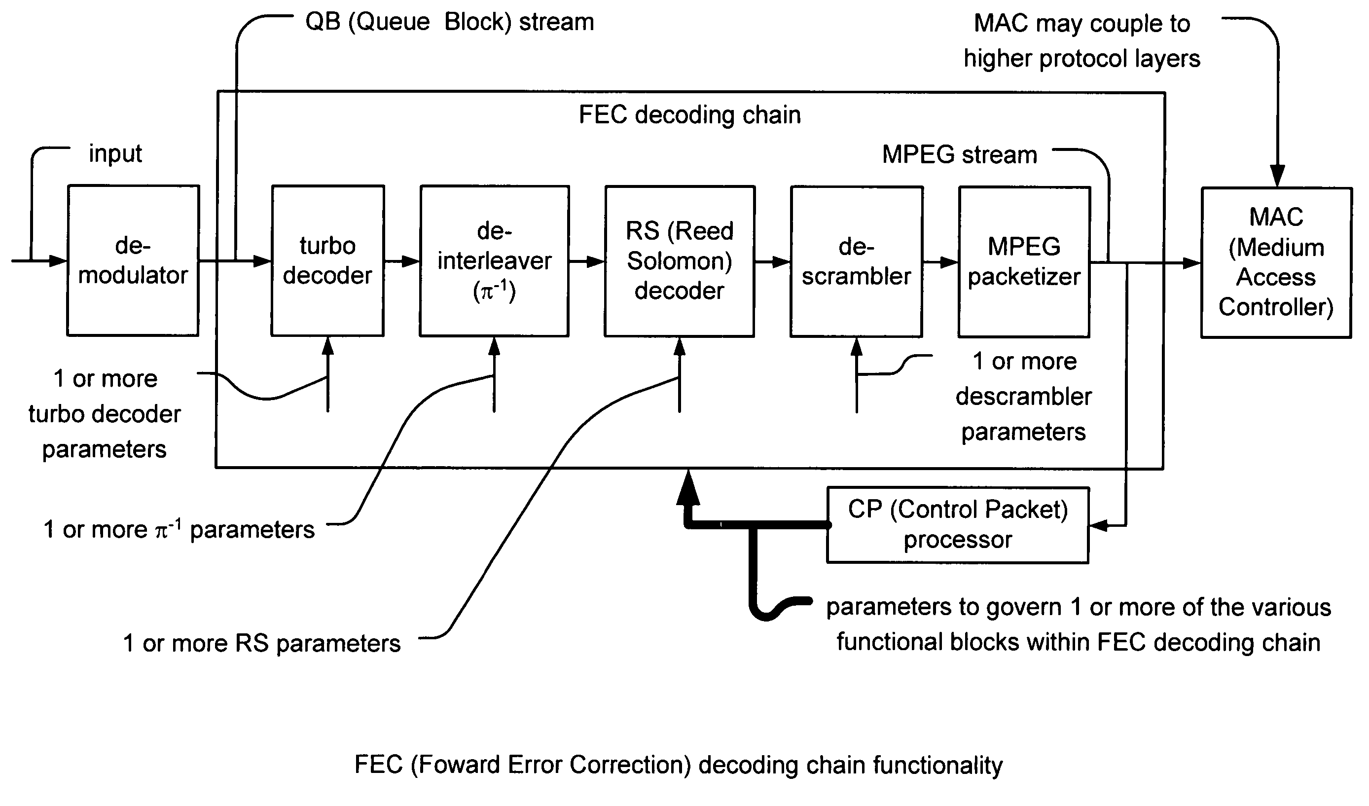
[0058]A novel solution of employing a parameter extraction functional block that follows the FEC (Forward Error Correction) decoding functional block is introduced. Information on the FEC decoding operational parameters is embedded in the packets that come out of the FEC decoding functional block so that it is protected by the inherent error correctional functionality and benefits provided by the FEC employed within the communication device. This packet that includes the FEC operational parameters is referred to as a CP (Control Packet). As one particular example, in the context where the communication device performs FEC decoding on an MPEG (Moving Picture Experts Group (Note: this group is an International Standards Organisation / International Electrotechnical Commission)) stream (e.g., an MPEG-2 transport stream in some instances), the CP is referred to as a CP MPEG block within the MPEG stream. Clearly, other types of communication systems and protocols could also benefit from va...


PUM


Abstract

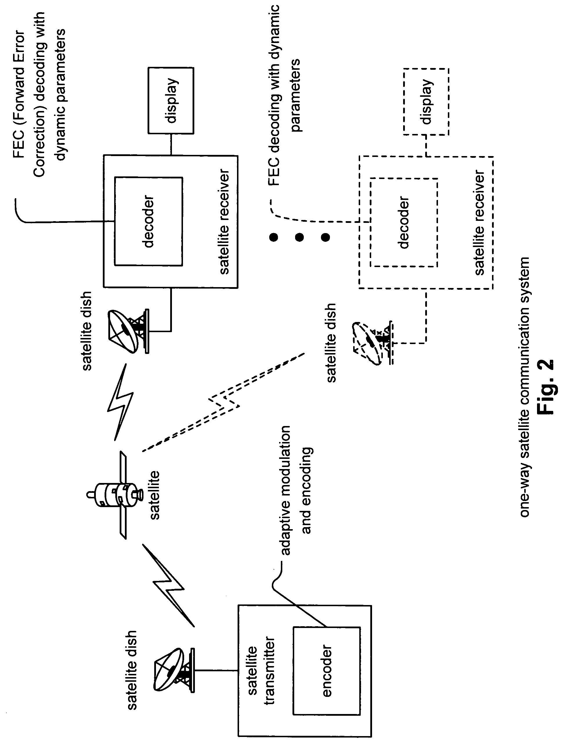
FEC (Forward Error Correction) decoder with dynamic parameters. A novel means by which FEC parameters may be encoded into, and subsequently extracted from, a signal stream to allow for adaptive changing of any 1 or more operational parameters that govern communications across a communication channel. FEC parameters are encoded directly into a data frame such that the data frame is treated identical to all other data frames within the signal stream. When the data frame actually includes FEC parameters, it is characterized as a CP (Control Packet) type. For example, when decoding an MPEG stream, an MPEG block that includes FEC parameters, that MPEG block is characterized as a CP MPEG block. The means by which FEC parameters are encoded and extracted from the signal stream allows for much easier adaptive modification of the manner by which signal are encoded, modulated, and processed within a communication system.

Description

CROSS REFERENCE TO RELATED PATENTS / PATENT APPLICATIONS[0001]The present U.S. Utility patent application claims priority pursuant to 35 U.S.C. § 119(e) to the following U.S. Provisional Patent Application which is hereby incorporated herein by reference in its entirety and made part of the present U.S. Utility patent application for all purposes:[0002]1. U.S. Provisional Application Ser. No. 60 / 516,826, entitled “FEC (Forward Error Correction) decoder with dynamic parameters,” filed Monday, Nov. 3, 2003 (Nov. 3, 2003 ), pending.[0003]The following U.S. Utility patent application is hereby incorporated herein by reference in its entirety and is made part of the present U.S. Utility patent application for all purposes:[0004]1. U.S. Utility patent application Ser. No. 10 / 319,929, entitled “DOWNSTREAM TIME DOMAIN BASED ADAPTIVE MODULATION FOR DOCSIS BASED APPLICATIONS,” filed Dec. 12, 2002, pending.BACKGROUND OF THE INVENTION[0005]1. Technical Field of the Invention[0006]The invention re...

Claims


Application Information

Patent Timeline
Patent Type & Authority Patents(United States)
IPC IPC(8): H03M13/35H03M13/00H04L1/00H04L1/18
CPCH04B7/18582H04L1/0003H04L1/0009H04L1/0039H04L1/0045H04L1/0057H04L1/0065H04L1/0066H04L1/0075H04L1/0026H04L1/007H04L1/0072H03M13/114H03M13/2927H03M13/2948
Inventor SUZUKIKWENTUS, ALAN Y.KRAFFT, STEPHEN EDWARDEDDY, KEVIN M.JAFFE, STEVEN T.
Owner AVAGO TECH WIRELESS IP SINGAPORE PTE
Learn More