Device and method for continuous regulation of the erection of a tandem axle

a technology of tandem axles and devices, which is applied in the direction of belts/chains/gearrings, mechanical equipment, and gear control, etc., can solve the problems of uneven erecting of axle beams, uneven distribution of wheel load between front and rear wheels, and tandem axles or boogie axles

Inactive Publication Date: 2007-08-21
NAF NEUNKIRCHENER ACHSENFABRIK
View PDF9 Cites 10 Cited by
  • Summary
  • Abstract
  • Description
  • Claims
  • Application Information

AI Technical Summary

Benefits of technology

[0010]In an inventive device for regulating the erection of a tandem axle of a vehicle or a self-moving working machine, a drive axle is coaxially connected to a drive tandem axle through a ball ramp device, wherein the ball ramp device is comprised of a first ball ramp disk connected to an end of the drive tandem axle opposing an end of the drive axle, and a second ball ramp disk disposed in axially displaceable manner at the end of the drive tandem axle. The distance L between the second ball ramp disk and the first ball ramp disk is increased by a torque of the drive tandem axle counteracting the drive torque, wherein the second ball ramp disk is operationally connected to a piston, and a pressure with a value of P1 is produced in a volume by the axial movement of the second ball ramp disk, wherein P1 is passed to a control valve, and the control valve controls the level of a system pressure P3 or P4 depending on P1, and this resulting pressure with the value of P2 serves for controlling a compensating device for achieving a compensating torque counteracting the erection effect. Therein, the control valve is usually connected to a hydraulic circuit of a hydraulic pump of the vehicle or the self-moving working machine. However, it is also conceivable that an own, separate hydraulic circuit serves for controlling the compensating device. By measuring the torque of the drive tandem axle counteracting the drive torque through the ball ramp device, i.e. converting a torque into an axial movement, and producing a control pressure P1, it is possible to reliably prevent the unwanted erection of the tandem axle to a predeterminable extent, and additionally to allow for separate regulation of the erection effect of the individual tandem axles considering the respectively occurring current and actual torques. Therein, the resulting pressure P2 serving for controlling the compensating device, is directly dependent on (proportional to) the measured pressure P1.
[0011]In an advantageous development of the invention, the control valve is a controllable or non-controllable proportional valve. Thereby, it is possible to preadjust the level of the pressure introduced into the control valve by the hydraulic system according to the requirement. Therein, this adjustment can be effected once or continuously.
[0013]In another advantageous development of the invention, the compensating device is a rotary piston cylinder assembly, wherein a housing of a pressurizable rotary piston cylinder is fixedly connected to an axle housing of the drive axle, and a movable piston of the rotary piston cylinder drives a succeeding planetary gearing with a planetary axle and planet pinions, wherein the planetary axle of the planetary gearing is fixedly connected to the axle housing or the housing of the rotary piston cylinder, and the planet pinions act on a toothed wheel connected to the tandem axle housing. By interposing a rotary piston cylinder and the planetary gearing succeeding the rotary piston cylinder, it is possible to exert the introduced pressure P2 on the tandem axle housing. Therein, the rotational direction of the rotary piston is reversed by the planetary gearing upon pressurization such that corresponding counter-torques act on the tandem axle housing.
[0016]An inventive method for regulating the erection of a tandem axle of a vehicle or a self-moving working machine includes the following steps: (a) introducing a drive torque through a drive axle and a coaxial drive tandem axle and mechanically distributing the introduced torque to the wheels disposed in a tandem axle housing, wherein the drive axle is connected to the drive tandem axle through a ball ramp device, and the ball ramp device is comprised of a first ball ramp disk connected to an end of the drive tandem axle opposing an end of the drive axle, and a second ball ramp disk disposed in axially displaceable manner at the end of the drive axle; (b) measuring a torque of the drive tandem axle counteracting the drive torque by means of a pressure with a value of P1 produced by a piston, wherein the piston is operatively connected to the second ball ramp disk; (c) passing the pressure P1 to a control valve; and (d) regulating the level of the system pressure P3 or P4 depending on P1 and introducing the resulting pressure with a value of P2 into a compensating device for achieving a compensating torque counteracting the erection effect. By the method according to the invention, it is possible to reliably modify the unwanted erection of the tandem axle to a predeterminable extent on the one hand, and to allow for separate regulation of the erection effect of the individual tandem axles considering the respectively occurring torques on the other hand. By measuring the actually occurring torque opposing the drive torque, of the so-called erection effect through the ball ramp device and the piston operatively connected thereto with production of a control pressure P1, continuous transmission and monitoring of the actual erection effect and compensation thereof are possible.

Problems solved by technology

Tandem axles or also boogie axles have the disadvantage that the axle beam erects more or less independently of transmission ratios and the geometrical ratios when a torque is introduced.
Thereby, non-uniform distribution of the wheel load between the front and rear wheels results, which are disposed at the respective ends of the axle beams.
Since the described tandem axles are mainly used in forest machines, tipping trucks and graders, which especially operate in pathless terrain, this results in great restrictions during operation of the corresponding vehicles and in different tire wear.
However, this is disadvantageous in that the components within the axle beam have to transmit a high torque and thus are appropriately largely dimensioned.
Therefore, such axle beams become very expensive, heavy and lose ground clearance.
However, these devices are disadvantageous in that the back torque is not able to be adjusted in its magnitude and is always proportional to the input torque.
The front or rear wheel of the tandem axle, respectively, is not able to be intentionally lifted by this mechanism.
However, this is disadvantageous in that the external hydraulic cylinders are susceptible, since they are exposed to the environmental influences.
Additionally, the installation between vehicle frame and tandem beam is expensive and restricts the independent freedom of movement of the tandem axle.
Distinct control of the left and right sides is not possible.
However, this device is disadvantageous in that also herein the predefined and controllable pressure is always in a fixed ratio to a theoretically occurring erection torque.
Separate regulation of the erection effect of the individual tandem axles considering the respectively occurring actual torques is not possible.

Method used


Image

  • Device and method for continuous regulation of the erection of a tandem axle
  • Device and method for continuous regulation of the erection of a tandem axle
  • Device and method for continuous regulation of the erection of a tandem axle

Examples


Embodiment Construction

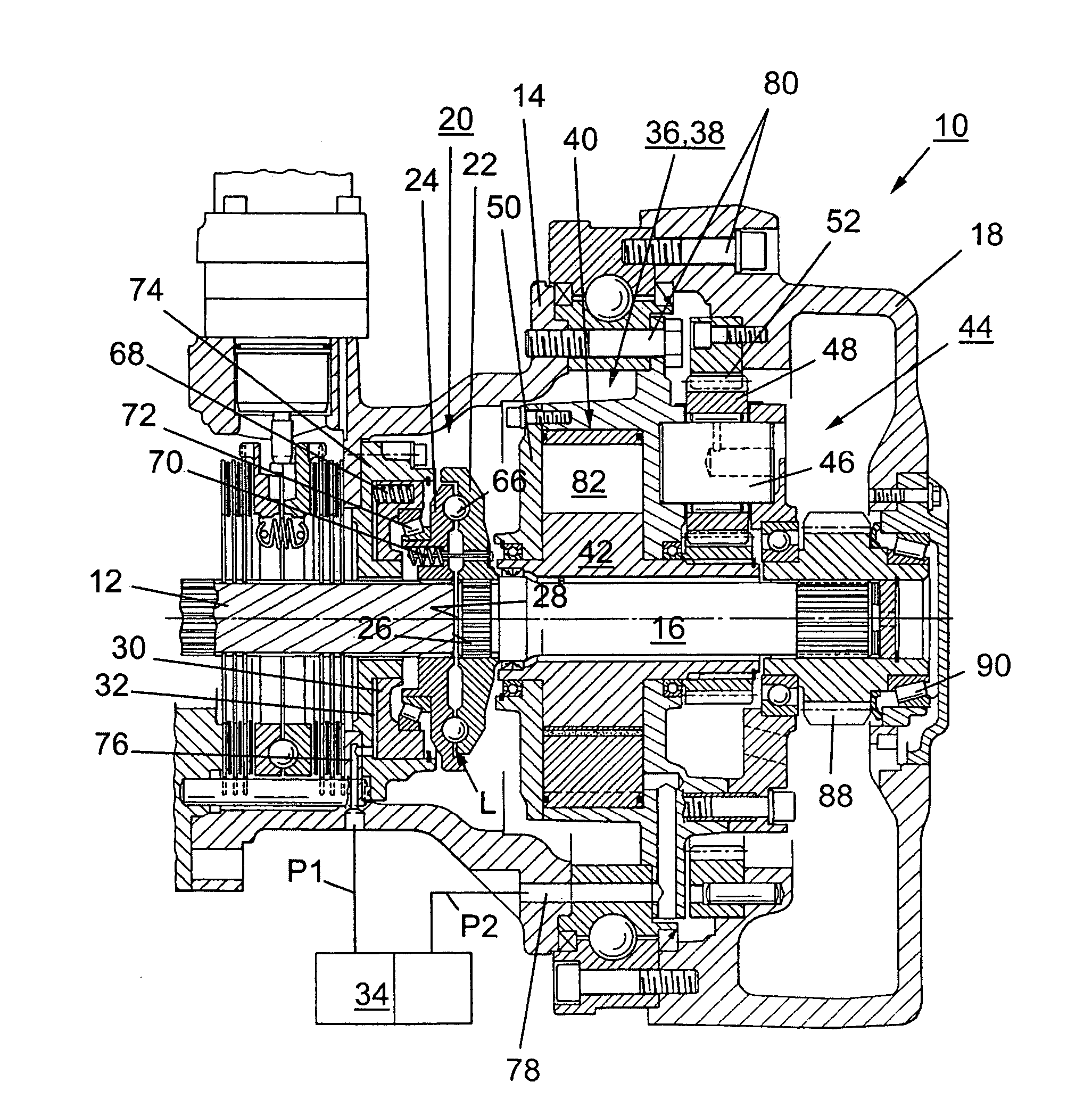
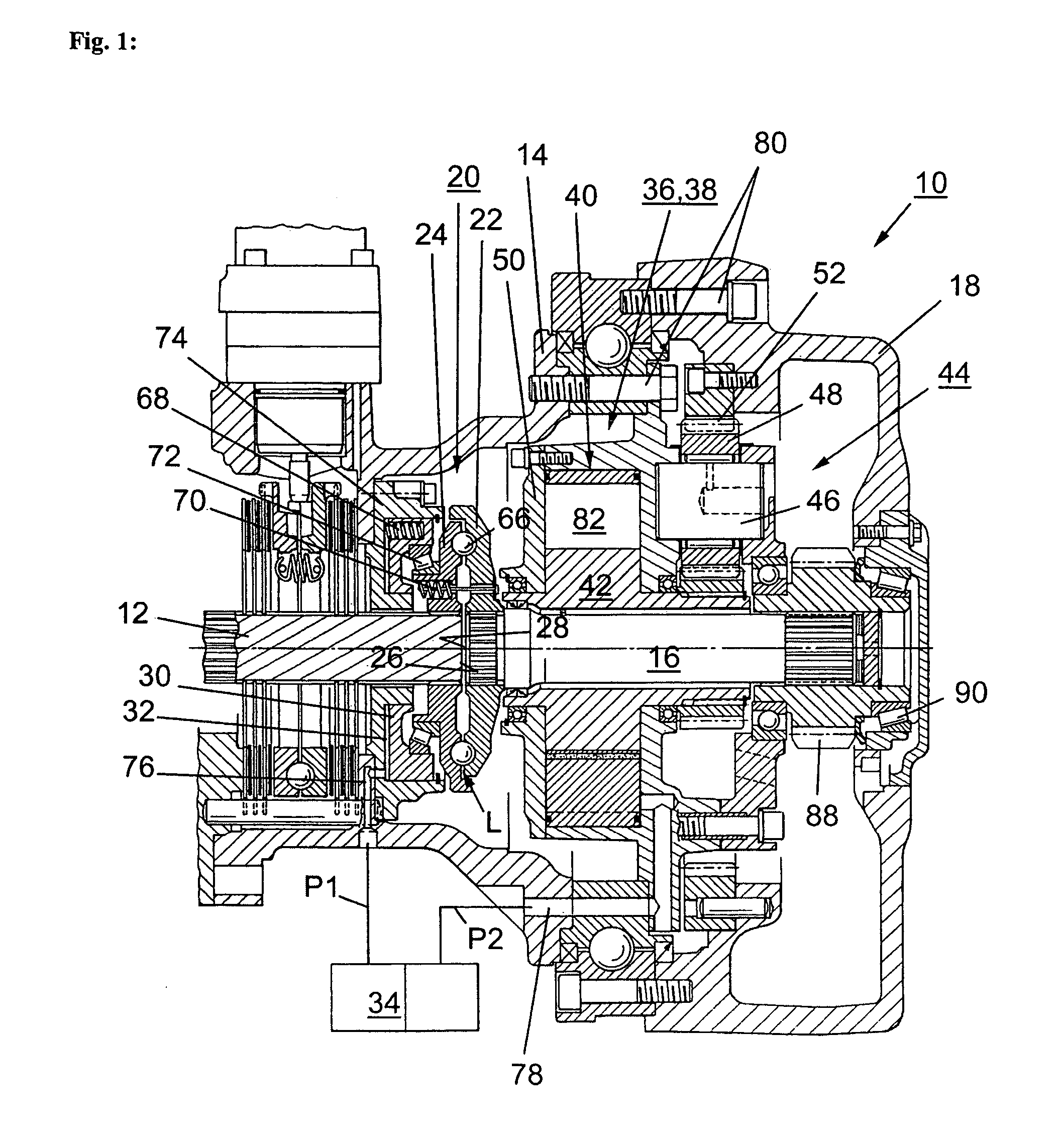
[0022]FIG. 1 shows a sectional view of an embodiment of the device 10 for continuously regulating the erection of a tandem axle of a vehicle or a self-moving working machine. Therein, the vehicle has a vehicle frame (not shown), on which an axle housing 14 of a drive axle 12 is disposed. At the respective ends of the drive axle 12, a drive tandem axle 16 having a movable tandem axle housing 18 is respectively positioned. Through the drive tandem axle 16, the torque introduced by the drive axle 12 is mechanically distributed to the wheels 84, 86 (see FIG. 2) disposed in the tandem axle housing. One recognizes that the drive axle 12 is coaxially connected to the drive tandem axle 16 through a ball ramp device 20. Therein, the ball ramp device 20 is comprised of a first ball ramp disk 22 connected to an end 26 of the drive tandem axle 16 opposing an end 28 of the drive axle 12, and a second ball ramp disk 24 disposed in axially displaceable manner at the end 28 of the drive tandem axle...


PUM


Abstract

The present invention relates to a device for continuously regulating the erection of a tandem axle of a vehicle or a self-moving working machine having a vehicle frame and at least one drive axle, wherein a tandem drive axle with a movable tandem axle housing is respectively disposed at the ends of the drive axle, and the torque introduced by the drive axle is mechanically distributed to the wheels disposed in the tandem axle housing through the drive tandem axle. Therein, the drive axle is coaxially connected to the drive tandem axle through a ball ramp device, wherein the ball ramp device is comprised of a first ball ramp disk connected to an end of the drive tandem axle opposing an end of the drive axle, and a second ball ramp disk disposed in an axially displaceable manner at the end of the drive tandem axle, and the distance L between the second ball ramp disk and the first ball ramp disk is increased by a torque of the drive tandem axle counteracting the drive torque, wherein the second ball ramp disk is operatively connected to a piston, and a pressure with a value of P1 is produced in a volume by the axial movement of the second ball ramp disk, wherein P1 is passed to a control valve, and the control valve controls the level of a system pressure P3 or P4 depending on P1, and a resulting pressure with the value of P2 serves for controlling a compensating device for achieving a compensating torque counteracting the erection effect. The invention further relates to a method for continuously regulating the erection of a tandem axle of a vehicle or a self-moving working machine.

Description

BACKGROUND OF THE INVENTION[0001]The present invention relates to a device for continuously regulating the erection of a drive tandem axle of a vehicle or a self-moving working machine having a vehicle frame and at least one drive axle, wherein a drive tandem axle having a movable tandem axle housing is respectively disposed at the ends of the drive axle, and the torque introduced by the drive axle is mechanically distributed through the drive tandem axle to the wheels disposed in the tandem axle housing. The invention further relates to a method for continuous regulation of the erection of a tandem axle of a vehicle or a self-moving working machine.[0002]Such devices for regulating the erection of a drive tandem axle of a vehicle or a self-moving working machine are known. Tandem axles or also boogie axles have the disadvantage that the axle beam erects more or less independently of transmission ratios and the geometrical ratios when a torque is introduced. Thereby, non-uniform dis...

Claims


Application Information

Patent Timeline
Patent Type & Authority Patents(United States)
IPC IPC(8): B62D61/10
CPCB60K17/36
Inventor AUER, ERNST
Owner NAF NEUNKIRCHENER ACHSENFABRIK
Why Eureka
Try Eureka