Pressure limiting valve with direct hydraulic damper

A pressure-limiting valve and hydraulic technology, applied in the direction of safety valves, balance valves, valve devices, etc., can solve problems such as inability to guarantee filling and damage, and achieve the effect of smooth guidance

Inactive Publication Date: 2011-06-08
沃尔夫冈·福斯
View PDF1 Cites 0 Cited by
  • Summary
  • Abstract
  • Description
  • Claims
  • Application Information

AI Technical Summary

Problems solved by technology

But the disadvantage is that this pressure balance chamber may run empty in the pressure balance state of the pressure limiting valve, so it cannot be guaranteed to be filled evenly when the valve is actuated.
Especially with pressure limiting valves of this type, damage can also occur due to hydraulic self-interference, but it is particularly disadvantageous that the above-mentioned opening and closing process of the pressure limiting valve is as uniform as possible through the operation of several closing parts.

Method used


Image

  • Pressure limiting valve with direct hydraulic damper
  • Pressure limiting valve with direct hydraulic damper
  • Pressure limiting valve with direct hydraulic damper

Examples


Embodiment Construction

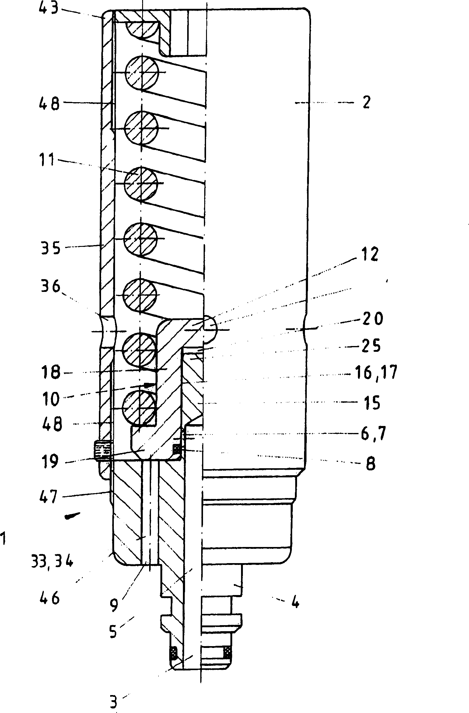
[0032] figure 1 A pressure limiting valve 1 is shown in section, the valve body 2 having the shape of a sleeve. A valve spring 11 is accommodated in this valve body 2 by a spring tray 12 , wherein a specially shaped spring tray 12 , which will be described in more detail below, stands on the connection 4 and guides the spring tray in a sliding manner on the connection. To this end, the connection 4 has a piston 15 and a sealing point between the stationary piston 15 and the movable spring tray 12 , which forms the so-called closing part 10 . The inlet port 3 of the valve body 2 is normally closed relative to the outlet port 9 by means of this closing element 10 . Only when a correspondingly high pressure occurs at the blind bore 5 of the joint 4, for example due to a rock impact, is this pressure liquid passed through the radial bores 6, 7 and the contact surfaces 16, 17 and the orifice 52 shown here and the damping chamber 20 are pressed into the valve spring tray 12, there...


PUM


Abstract

The invention relates to a pressure relief valve which involves direct hydraulic damping and protects hydraulic brace system from rock surges and other suddenly occurring overload. The pressure relief valve comprises a valve housing with a connection, wherein an input and an output sides of the valve housing are separated from one another by means of a closing part, which can be displaced against the force of a valve spring and comprises a seal, and are connected to one another when an overload situation occurs to drain the hydraulic fluid, wherein the closing part is formed by a piston, which is linked to the connection, and a valve spring retainer, which comprises said piston, is arranged displaceably thereon and accordingly has a cylindrical design, the seal is arranged in a groove, which is incorporated in a contact surface of the valve spring retainer at a distance from a base of the valve spring retainer, which guarantees a sufficiently large sealing surface beneath radial bores on the piston.

Description

technical field [0001] The present invention relates to a pressure limiting valve for protecting hydraulic units from harmful overloading effects, in particular for protecting hydraulic drilling and mining machines from rock impact and other sudden overloading effects, the pressure limiting valve has a belt The valve body of the joint, wherein the inlet and outlet ends of the valve body are separated from each other by a closing part that slides against the force of the valve spring and has a seal and are connected to each other for the discharge of pressurized fluid in the event of an overload. Background technique [0002] Such a pressure limiting valve is known from DE 19946848 A1. Especially in underground coal mining for space protection, protective mining supports with one or more hydraulic struts are used in the support, which have to be protected against the above-mentioned overloads by means of pressure limiting valves. These pressure-limiting valves are calculated...

Claims


Application Information

Patent Timeline
Patent Type & Authority Patents(China)
IPC IPC(8): F16K17/04
CPCF16K17/046F16K15/142Y10T137/7842Y10T137/785Y10T137/7925Y10T137/7929
Inventor 沃尔夫冈·福斯
Owner 沃尔夫冈·福斯
Why Eureka
Try Eureka