Optical system controller for video camera

a video camera and optical system technology, applied in the field of optical system controllers for video cameras, can solve the problems of focusing lenses, user's inability to know instant positions, and the user's focusing and zooming lenses cannot be known any longer, so as to achieve a convenient display

Inactive Publication Date: 2007-08-21
SONY CORP
View PDF5 Cites 25 Cited by
  • Summary
  • Abstract
  • Description
  • Claims
  • Application Information

AI Technical Summary

Benefits of technology

[0021]According to the present invention, the optical system controller for a video camera functions in the following manner. The display in response to the position of the focusing lens in the lens barrel is produced by the first optical display means arranged near the focus adjusting movable mechanism placed around the lens barrel. The display in response to the position of the zooming lens in the lens barrel is produced by the second optical display means arranged near the zoom adjusting movable mechanism placed around the lens barrel. The display in response to the opening of the iris diaphragm in the lens barrel is produced by the third optical display means arranged near the zoom adjusting movable mechanism placed around the lens barrel. The first optical display means is close to the focus adjusting movable mechanism placed around the lens barrel. The second optical display means is close to the zoom adjusting movable mechanism placed around the lens barrel. The third optical display means is close to the diaphragm adjusting movable mechanism placed around the lens barrel. Such arrangement as mentioned above permits the user of the video camera to watch directly and certainly the display of each of the optical display means.
[0022]Thus, even in the case where a video camera has an electronic control system for the movable optical system including a zooming lens, focusing lens, and iris diaphragm in the lens barrel, the user of the video camera can recognize accurately and rapidly the positions of the focusing and zooming lenses and the opening of the iris diaphragm in the lens barrel by means of the displays produced by the first, second, and third optical display means, while he is not watching the view finder or monitor of the video camera provided with the optical system controller.
[0023]Each of the first, second, and third optical display means produces its color display by means of light-emitting elements in array. Therefore, the first, second, and third optical display means arranged around the lens barrel produce an easily visible display without requiring any special illuminating means. Consequently, the user of the video camera provided with the optical system controller can recognize adequately and very easily the positions of the focusing and zooming lenses and the opening of the iris diaphragm in the lens barrel.

Problems solved by technology

The disadvantage of the electronic control system is that the position of the focusing lens and zooming lens and the opening of the iris diaphragm do not correspond directly to the amount of rotation of the movable mechanisms for adjustment of the focusing lens, zooming lens, and iris diaphragm.
In practice, however, the user of the video camera often leaves his eye from the view finder or monitor during his camera operation, because the user tires of continuously watching the view finder or monitor for a long time and the user sometimes needs to see his surrounding scene.
However, once the user of the video camera turns his eye away from the view finder or monitor, he cannot know any longer the positions of the focusing and zooming lenses and the opening of the iris diaphragm in the lens barrel.
In other words, the user of the video camera cannot know instantly the positions of the focusing and zooming lenses and the opening of the iris diaphragm while he is waiting for the chance of taking pictures, with his eye turned away from the view finder or monitor.
As the result, it is difficult for him to set up immediately the adequate positions of the focusing and zooming lenses and the adequate opening of the iris diaphragm in the case of decisive moment for photographing while he is waiting for a chance.
Thus, he would miss the chance to take sharp images at the decisive moment.
This situation is serious if the user of the video camera is a professional camera man.
Also, it is not unusual for a professional camera man to take pictures without watching the view finder or monitor; however, in such a case, too, he cannot know the positions of the focusing and zooming lenses and the opening of the iris diaphragm.

Method used


Image

  • Optical system controller for video camera
  • Optical system controller for video camera
  • Optical system controller for video camera

Examples


Embodiment Construction

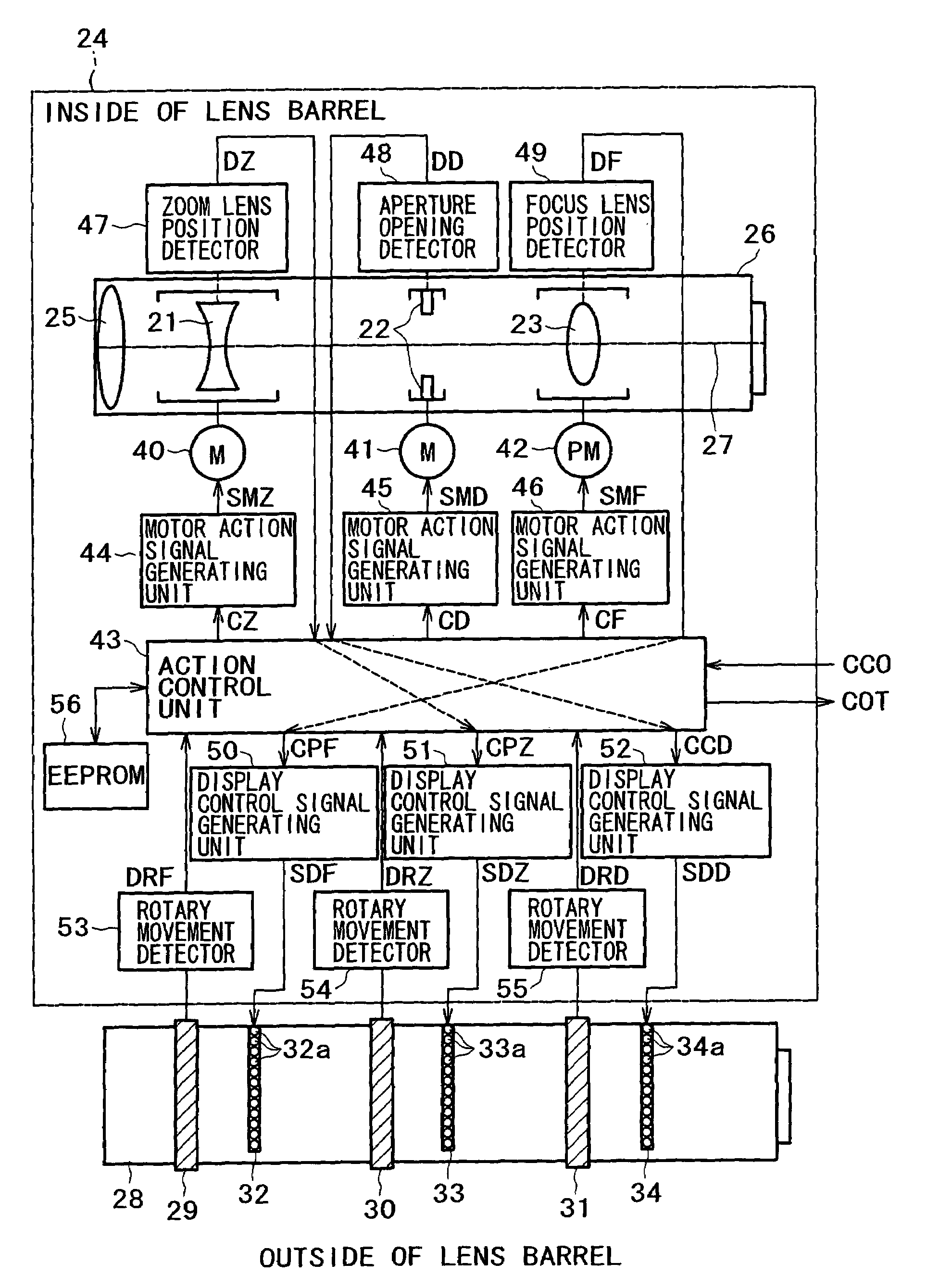
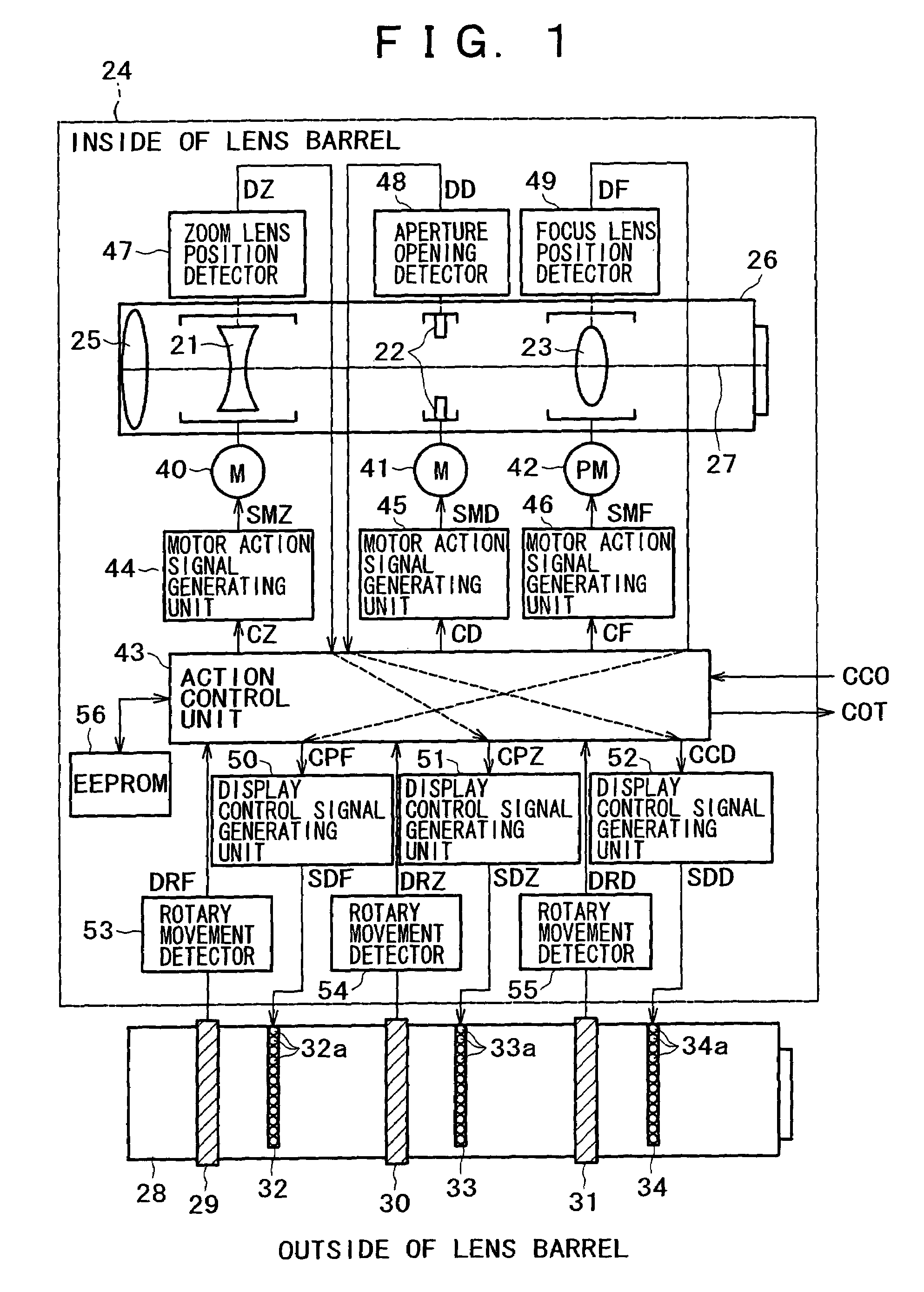
[0034]FIG. 1 is a block diagram showing the construction of one embodiment of the optical system controller of a video camera according to the present invention.

[0035]In FIG. 1 illustrating one embodiment of the present invention, there is shown a lens barrel 24 which has a built-in movable optical system including a fore-end lens 25, a zooming lens 21, an iris diaphragm 22, and a focusing lens 23. These optical components are held by a cylindrical part 26.

[0036]In the cylindrical part 26 are sequentially arranged the fore-end lens 25, zooming lens 21, iris diaphragm 22, and focusing lens 23, from front to rear, along the common optical axis 27. While the fore-end lens 25 is fixed, the zooming lens 21 and focusing lens 23 are movable back and forth, over a predetermined distance, in the cylindrical part 26 in the direction along the common optical axis 27.

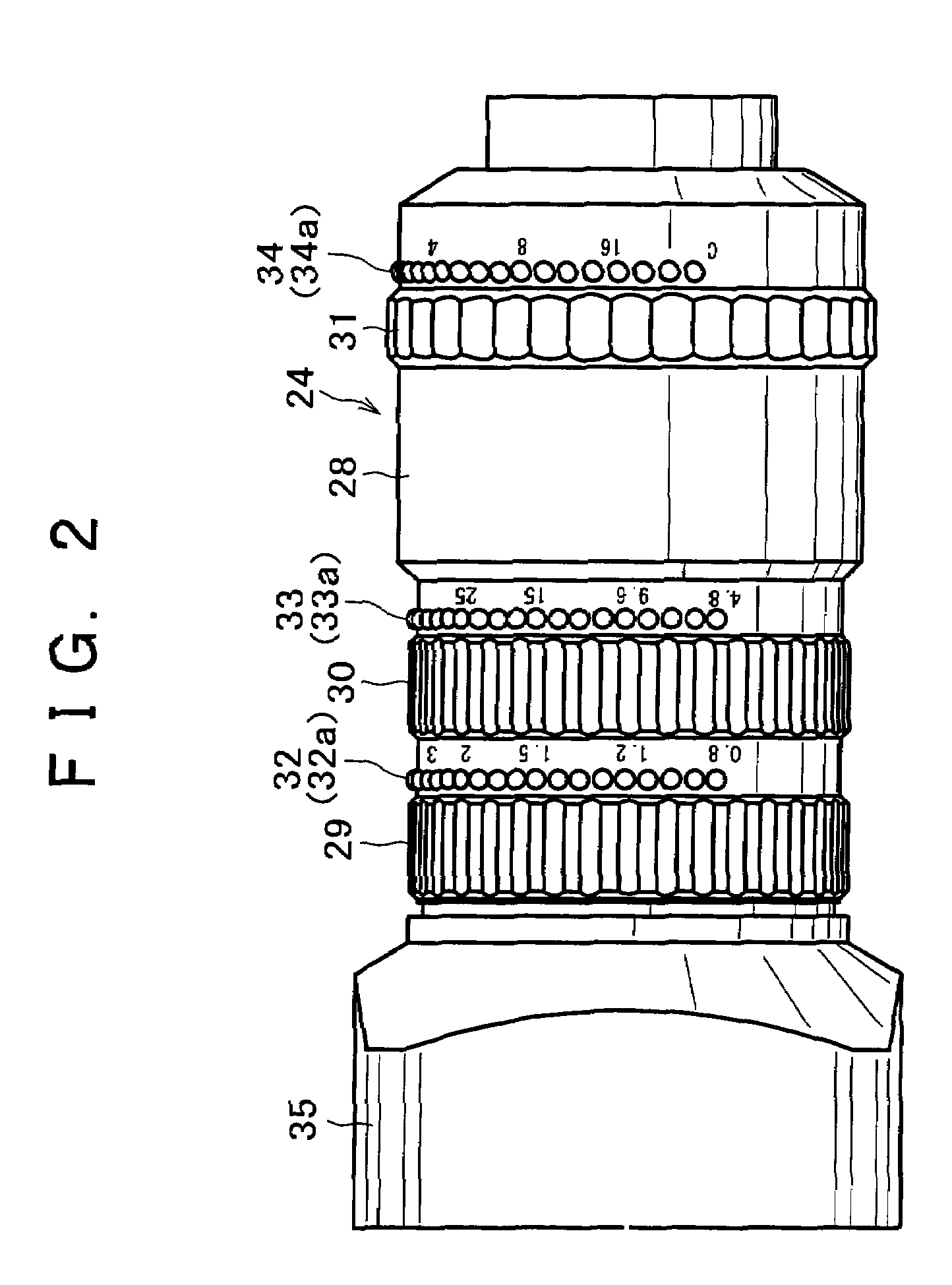
[0037]On the outer surface 28 of the lens barrel 24 are arranged a focus adjusting movable mechanism 29, a zoom adjusting movable...


PUM


Abstract

An optical system controller for a video camera having a lens barrel in which is arranged a movable optical system and on the outer surface of which is arranged an adjusting movable mechanism for the movable optical system. It permits the user to recognize easily and directly the display indicating the position of the movable optical system or the opening of the aperture in the lens barrel. The optical system controller consists of the focus adjusting movable mechanism, the zoom adjusting movable mechanism, and the aperture adjusting movable mechanism, which are arranged on the outer surface of the lens barrel; it also consists of the focus lens position display, the zoom lens position display, and the aperture opening display, which constitute the optical display means arranged respectively in the vicinity of the movable mechanisms; the focus lens position display performs optical display in response to the position of the focus lens in the lens barrel, the zoom lens position display performs optical display in response to the position of the zoom lens in the lens barrel, and the aperture opening display performs optical display in response to the opening of the iris diaphragm in the lens barrel.

Description

BACKGROUND OF THE INVENTION[0001]1. Field of the Invention[0002]The present invention relates to an optical system controller for a video camera which has, as a part thereof, a lens barrel in which is arranged a movable optical system including a zoom lens, an iris diaphragm, and a focusing lens, and on the outer surface of which is arranged a movable mechanism for focusing adjustment, zooming adjustment, and aperture adjustment.[0003]2. Description of the Prior Art[0004]The video camera permits light rays from a subject to pass through an optical system having lenses and enter an imaging unit, so that the image of a subject is projected onto the image plane of the imaging unit. For the image of a subject to be focused sharply at all times, the video camera is required to have autofocusing and zooming capability. (Zooming is the movement of lenses that continuously changes (within a certain range) the magnification of the image of a subject which is projected onto the image plane.) ...

Claims


Application Information

Patent Timeline
Patent Type & Authority Patents(United States)
IPC IPC(8): H04N5/238G02B7/02G02B7/08G02B7/10G03B17/18H04N5/225H04N5/232
CPCH04N5/2254H04N23/55H04N23/67
Inventor TERADA, HIROTSUGU
Owner SONY CORP
Why Eureka
Try Eureka