Method for establishing a connection from a terminal of a communication network to a network-external connection destination, and associated apparatus and network

Inactive Publication Date: 2007-08-21
SIEMENS AG
View PDF12 Cites 54 Cited by
  • Summary
  • Abstract
  • Description
  • Claims
  • Application Information

AI Technical Summary

Benefits of technology

[0008]One major advantage of the present invention is that no additional signaling is required between central connection controllers of different communication networks in order to establish a connection. It is, therefore, also unnecessary for the connection controller to have any complex interface to network-external connection controllers. It is nevertheless possible to utilize the full range of data packet transport capabilities of a communication network relaying the connection to the connection destination. It is, moreover, also possible to establish connections to connection destinations that are not controlled by any connection controller.
[0009]According to one advantageous embodiment of the method according to the present invention, the gateway device can register as a network-internal connection destination with the connection controller under one or more logical addresses that identify one or more network-external connection destinations. An address table for network-internal connection destinations of the connection controller can, thus, be automatically updated. As a result, only administration of the gateway device is necessary to manage a number of different network-external conne

Problems solved by technology

However, such signaling between different gatekeepers requires a high implementation effort, especially if there are also one or more further packet-based communication networks between the first and second communication networks.
Another disadvantage of the

Method used


Image

  • Method for establishing a connection from a terminal of a communication network to a network-external connection destination, and associated apparatus and network
  • Method for establishing a connection from a terminal of a communication network to a network-external connection destination, and associated apparatus and network

Examples


Embodiment Construction

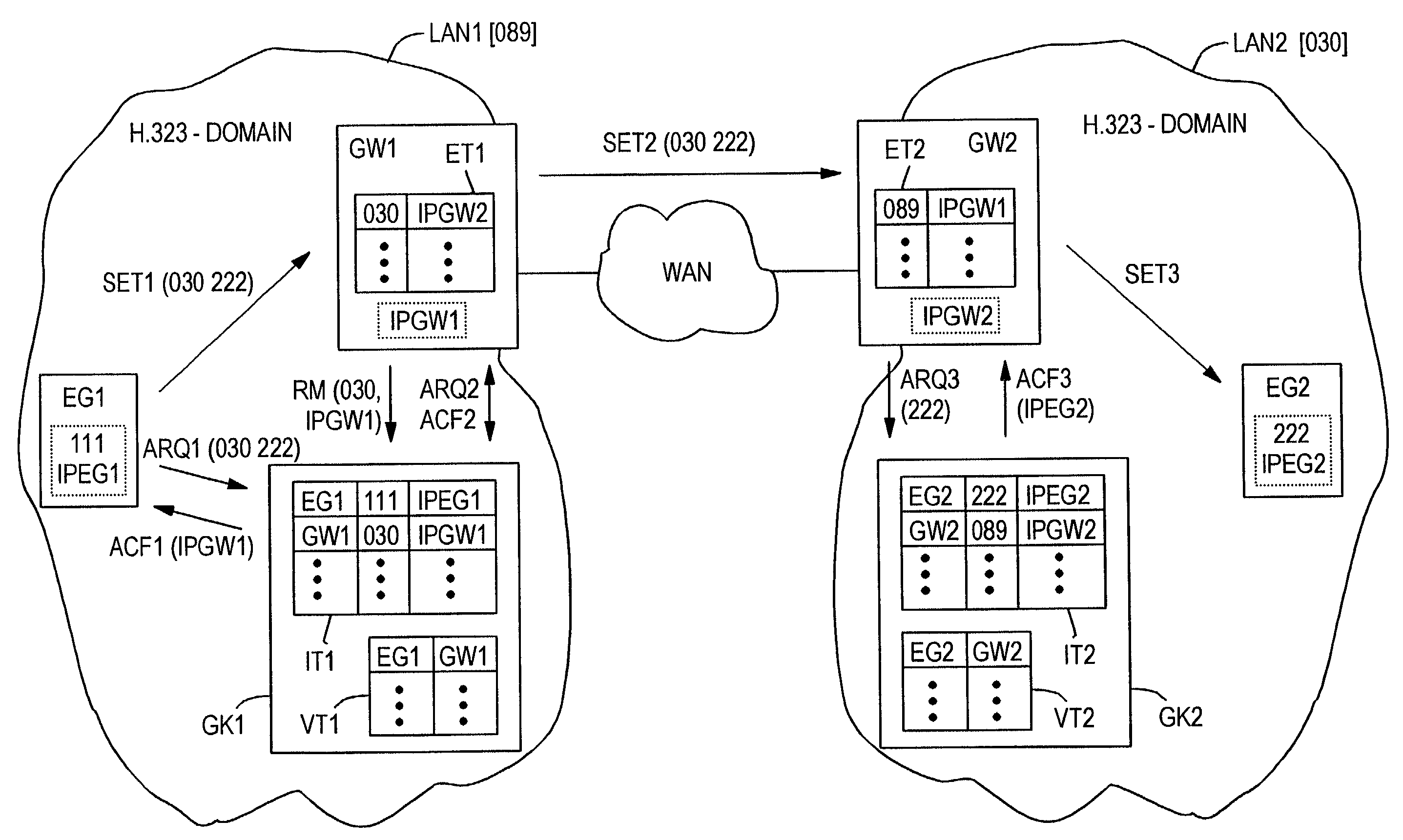
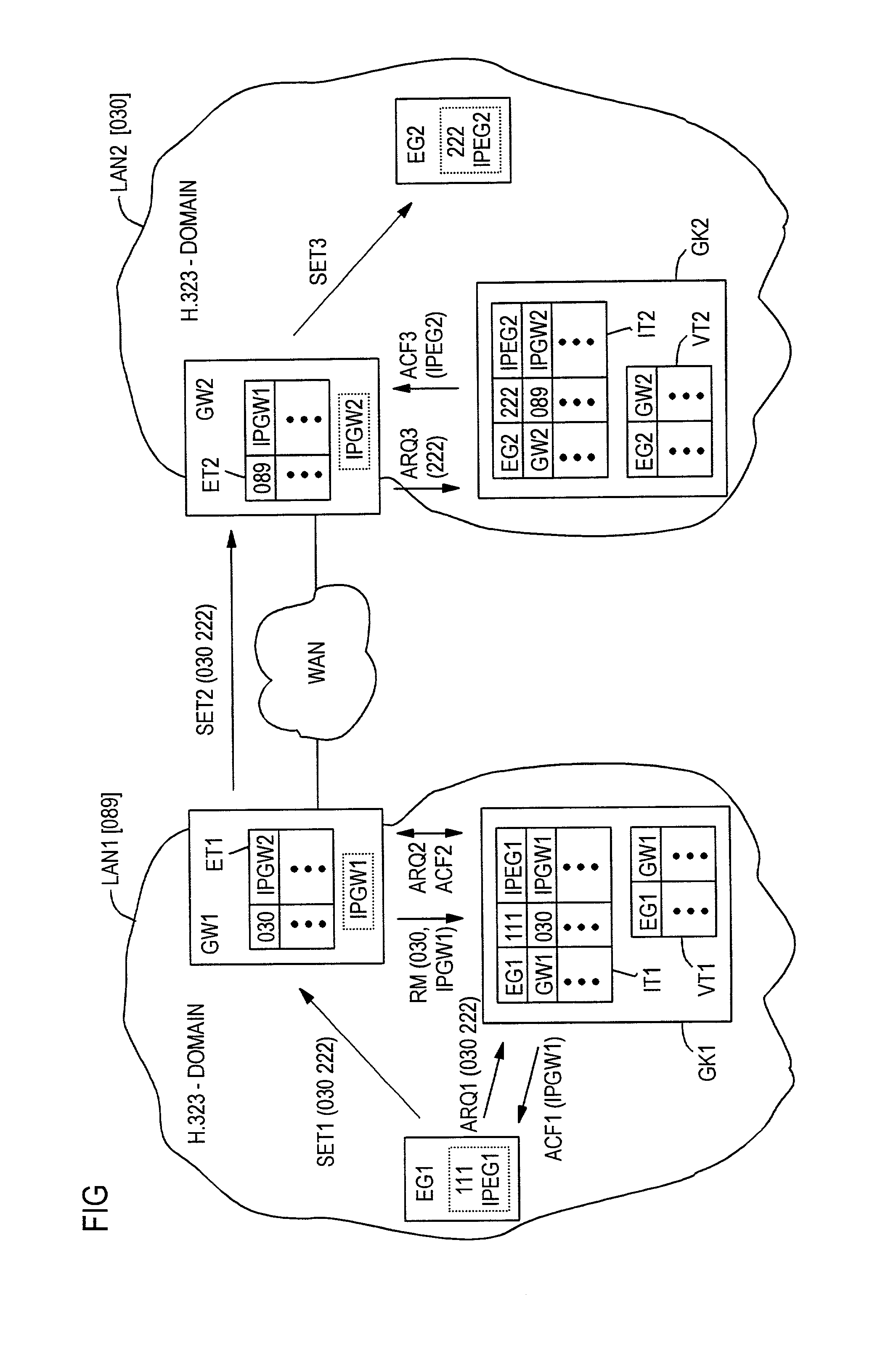
[0015]Diagrammatically illustrated in FIG. 1 are two communication networks LAN1 and LAN2 designed as local area networks which are linked via a wide area network WAN; e.g., the Internet.

[0016]The local area networks LAN1 and LAN2 and the wide area network WAN support packet-based data transport in each case. In the present exemplary embodiment, the data packet transmission in the local area networks LAN1 and LAN2 and in the wide area network WAN is based, in each case, on the so-called Internet Protocol (IP), with which data packets are forwarded through the respective communication network LAN1, LAN2 or WAN on the basis of an IP transport address contained therein.

[0017]It is assumed for the present exemplary embodiment that the local area network LAN1 is located in the Munich telephone code area having the public prefix number 089 and the local area network LAN2 is located in the Berlin telephone code area having the public prefix number 030. Accordingly, the prefix number 089 is...


PUM


Abstract

A method for establishing a connection from a network-internal terminal of a communication network, the network-internal connections of which are managed by a connection controller, to a network-external connection destination, wherein the connection is established via a gateway device which is registered in the connection controller under the logical address of the network-external connection destination, and on the basis of the logical destination address, the connection controller establishes a network-internal connection from the terminal to the gateway device, and in the gateway device itself, a network-externally valid transport address is assigned to the logical destination address, on the basis of which transport address the connection is relayed to the network-external connection destination.

Description

BACKGROUND OF THE INVENTION[0001]In modern communication systems, connections such as for voice, video or multimedia communication are increasingly being carried over packet-based communication networks, such as local area networks (LAN) or wide area networks (WAN) So-called Internet telephony, for example, often also referred to as “Voice over Internet Protocol” (VoIP), is based on this technology.[0002]In such packet-based communication networks, the user data to be transmitted is split into individual data packets which are provided with a transport address that identifies the respective connection destination. On the basis of the transport address the data packets are forwarded in the communication network to the respective connection destination independently of each other to a large extent.[0003]A central connection controller is often employed in packet-based communication networks. As a rule, such a connection controller manages the establishment and clearing of connections,...

Claims


Application Information

Patent Timeline
IPC IPC(8): H04L12/66H04L29/06
CPCH04L29/06H04L65/1043H04L65/104H04L65/1009H04L65/103H04L29/06027H04L65/1106H04L9/40H04L65/1101
Inventor SALLER, FRANZ
Owner SIEMENS AG
Why Eureka
Try Eureka