
Optical waveguide grating coupler with varying scatter cross sections

a technology of optical waveguides and scatter cross sections, applied in the field of integrated optics, can solve the problems of impracticality of fabricating elongated scattering elements smaller than what lithographic processes can provide, and the scatter cross section often oscillates, so as to reduce the scatter cross section, and increase the scatter cross section

Active Publication Date: 2007-08-21
CISCO TECH INC
View PDF10 Cites 25 Cited by
  • Summary
  • Abstract
  • Description
  • Claims
  • Application Information

AI Technical Summary

Benefits of technology

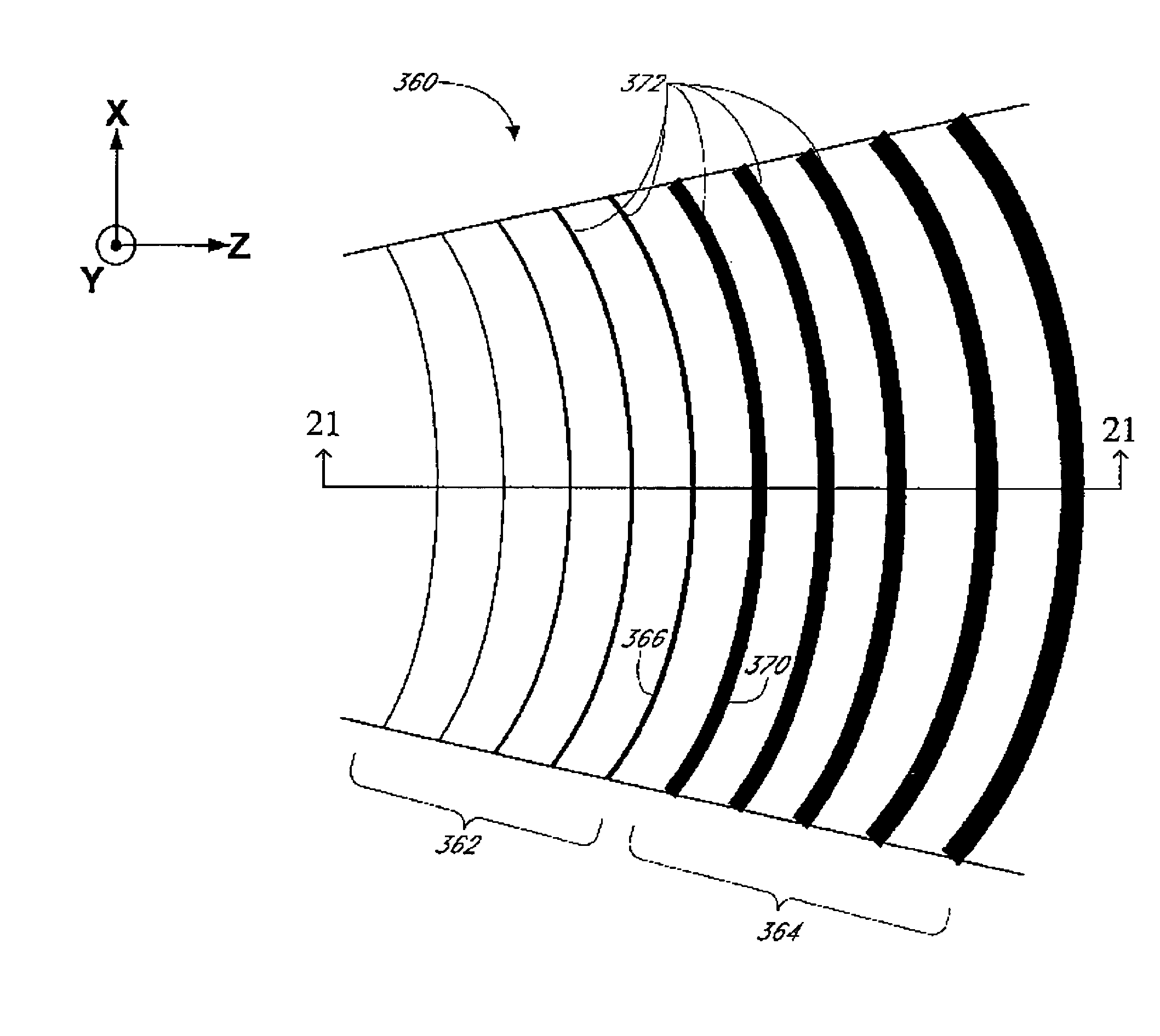
[0016]Another aspect of the invention comprises an integrated optical apparatus comprising a planar waveguide having an elongate guiding portion and a grating coupler. The coupler has first and second ends, with the first end adjacent the elongate guiding portion. The coupler includes a grating for diffracting light into or out of the coupler. The grating comprises a plurality of elongate scattering elements having respective scatter cross-sections. At least one of the elongate scattering elements is segmented so as to reduce the scatter cross-section of the at least one elongate scattering element. The at least one segmented elongate scattering element is disposed adjacent the first coupler end. The coupler further comprises a first unsegmented elongate scattering element adjacent the at least one segmented elongate scattering element. The first unsegmented elongate scattering element has a greater scatter cross-...

Problems solved by technology

However, when the grating coupler induces stronger scattering of light, the scatter cross-section often times oscillates as a function of the size of the scattering element.
One possible reason for such oscillation is due to the interference of reflected light from the various interfaces associated with the grating coupler.
The lower limit stems from the lithographic limit of the elongate scattering element, i.e., it is impractical to fabricate elongate scattering elements smaller than what lithographic processes can provide.

Method used


Image

  • Optical waveguide grating coupler with varying scatter cross sections
  • Optical waveguide grating coupler with varying scatter cross sections
  • Optical waveguide grating coupler with varying scatter cross sections

Examples


Embodiment Construction

)

[0041]Although this invention will be described in terms of certain preferred embodiments, other embodiments that are apparent to those of ordinary skill in the art, including embodiments that do not provide all of the benefits and features set forth herein, are also within the scope of this invention. Accordingly, the scope of the invention is defined only by reference to the appended claims.

A. Planar Waveguides and Integrated Optical Chips

[0042]In general, optical waveguides comprise a core region comprising material that is at least partially transparent. This core region is surrounded by a cladding region that confines light within the core region. Some optical energy, often referred to as the evanescent energy or the evanescent field, however, may exist outside the core region and within the cladding region.

[0043]In certain waveguides, the core region comprises a first medium having a first refractive index, and the cladding region or cladding comprises a second medium having ...


PUM


Abstract

Various configurations of elongate scattering elements in an optical waveguide grating coupler for coupling light between a planar waveguide and an optical element such as an optical fiber, where the light may have a Gaussian intensity distribution. The elongate scattering elements are preferably curved, and in some embodiments, the scattering elements have elliptically curved shape. One or more of the elongate scattering elements may be segmented into various geometrical shapes, such as rectangular, square, circular and elliptical. The elongate scattering elements have at least one characteristic selected from the group consisting of grating width, height, spacing, depth and index of refraction forming the elongate scattering elements, where the magnitude of the at least one characteristic varies irregularly with position along the guiding portion of the optical waveguide grating coupler.

Description

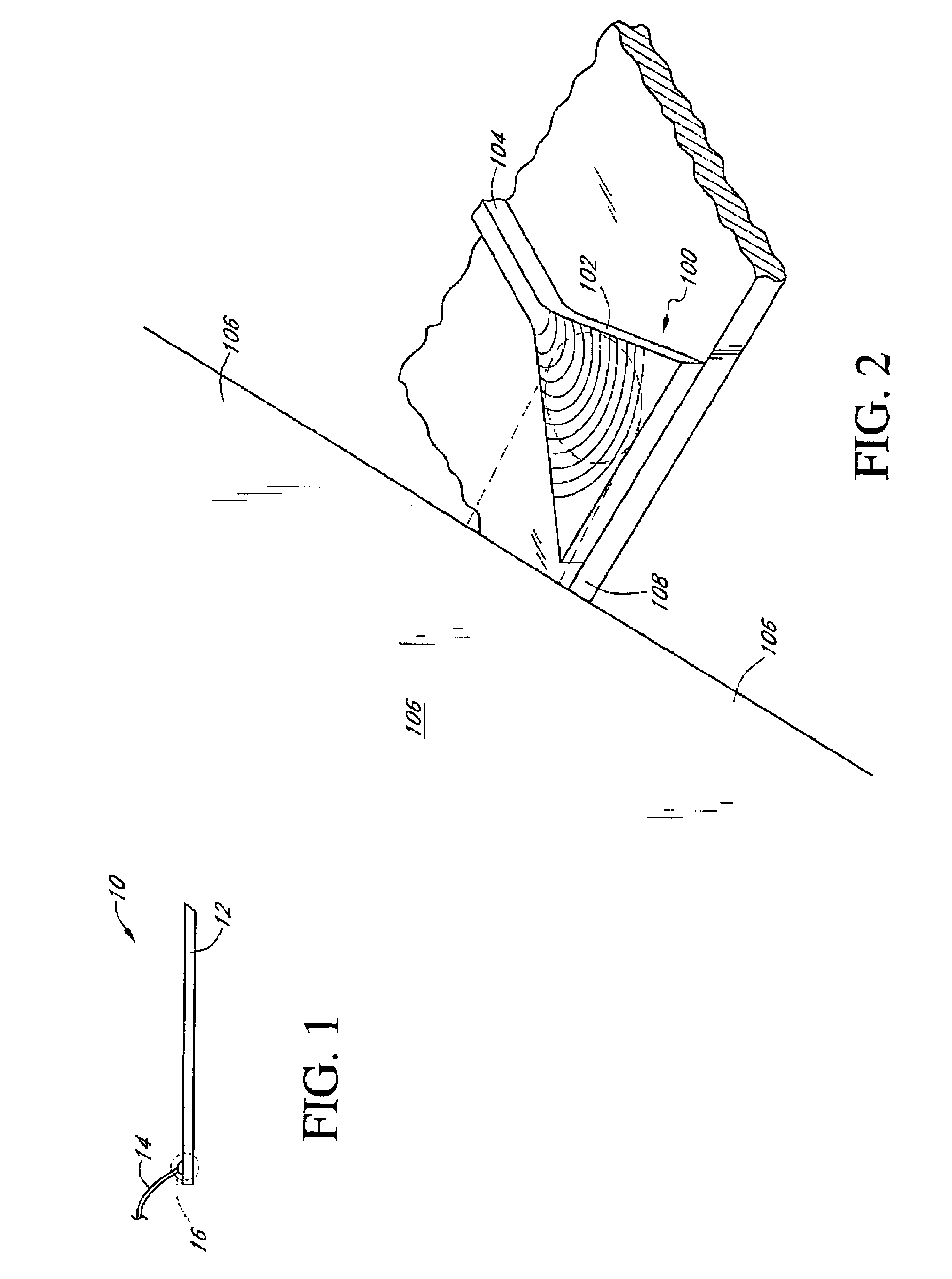
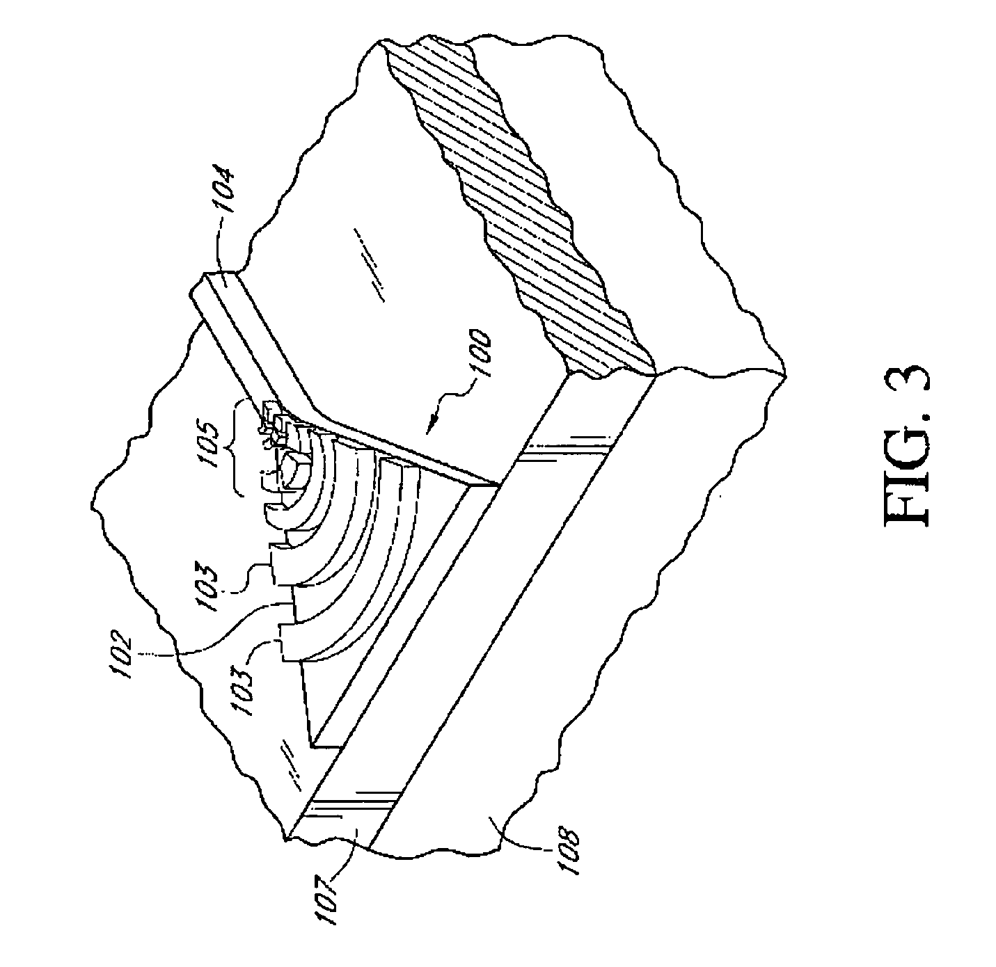
CROSS REFERENCE TO RELATED APPLICATIONS[0001]This application claims the benefit of U.S. Provisional Applications Nos. 60 / 446,842, 60 / 446,843, 60 / 446,844, 60 / 446,845, 60 / 446,846 and 60 / 446,847, all of them filed on Feb. 11, 2003.FIELD OF INVENTION[0002]The present invention relates to integrated optics, and more particularly, to an optical waveguide grating coupler with scattering elements of various configurations.BACKGROUND OF INVENTION[0003]Light offers many advantages when used as a medium for propagating information, the foremost of which are increased speed and bandwidth. In comparison with electrical signals, signals transmitted optically can be switched and modulated faster and can include an even greater number of separate channels multiplexed together. For these, as well as other reasons, light wave transmission along optical fibers is widespread.[0004]Light can be propagated through planar waveguide structures as well as optical fibers. Planar waveguide structures having ...

Claims


Application Information

Patent Timeline
IPC IPC(8): G02B6/34
CPCG02B6/124G02B6/30G02B6/34G02B2006/12195
Inventor GUNN, III, LAWRENCE C.PINGUET, THIERRY J.RATTIER, MAXIME J.
Owner CISCO TECH INC
Learn More