

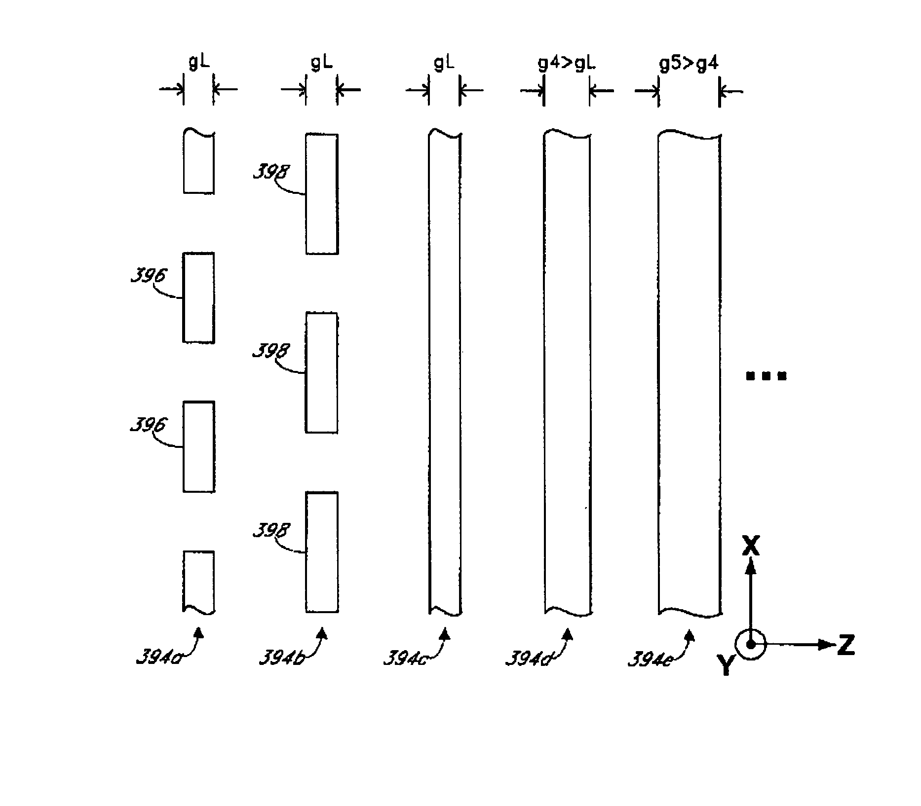
Optical waveguide grating coupler with varying scatter cross sections
a technology of optical waveguides and scatter cross sections, applied in the field of integrated optics, can solve the problems of impracticality of fabricating elongated scattering elements smaller than what lithographic processes can provide, and the scatter cross section often oscillates, so as to reduce the scatter cross section, and increase the scatter cross section
- Summary
- Abstract
- Description
- Claims
- Application Information
AI Technical Summary
Benefits of technology
Problems solved by technology
Method used
Image

Examples
Embodiment Construction
)
[0041]Although this invention will be described in terms of certain preferred embodiments, other embodiments that are apparent to those of ordinary skill in the art, including embodiments that do not provide all of the benefits and features set forth herein, are also within the scope of this invention. Accordingly, the scope of the invention is defined only by reference to the appended claims.
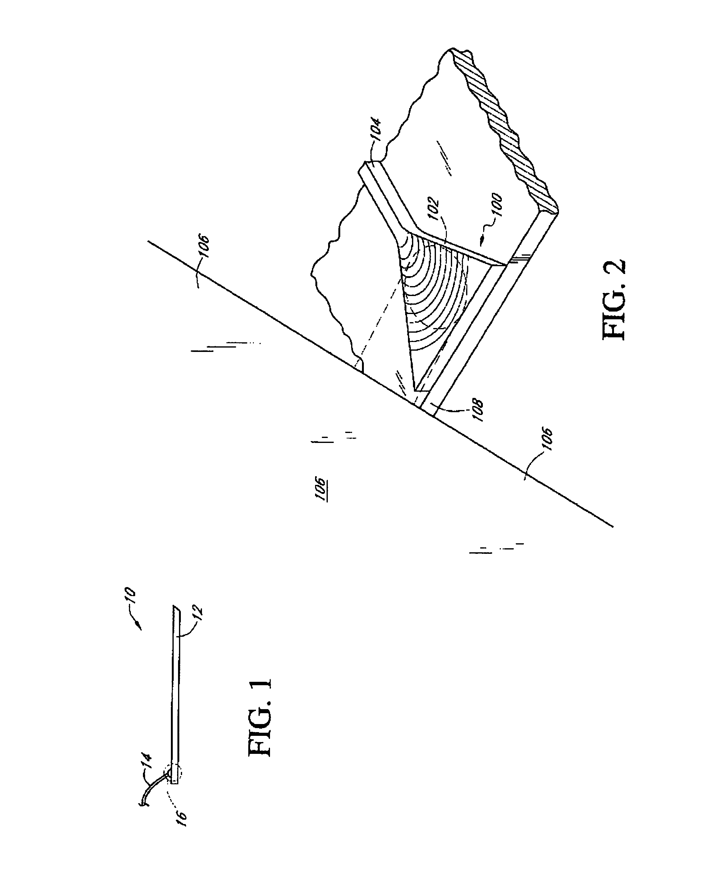
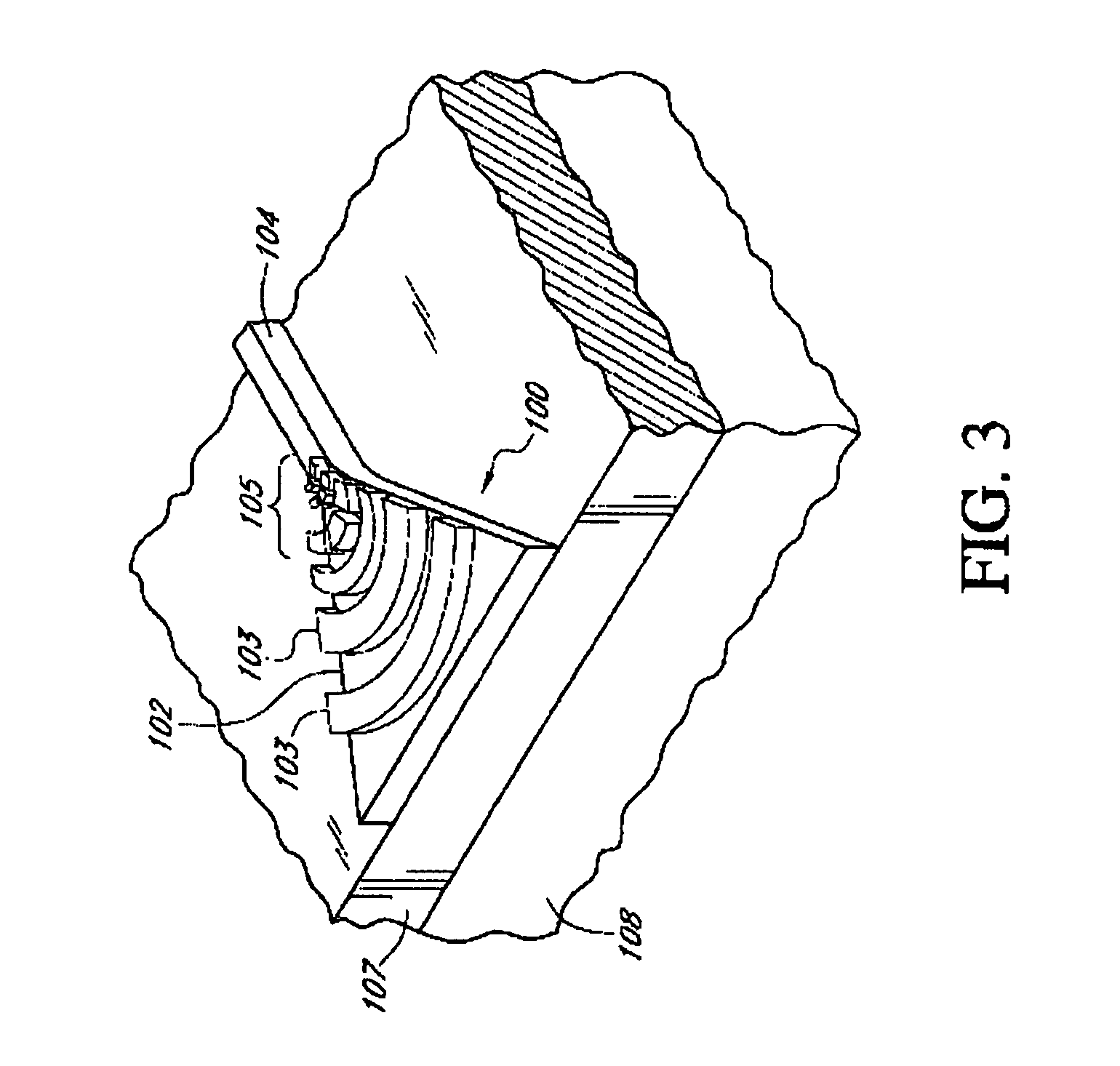
A. Planar Waveguides and Integrated Optical Chips
[0042]In general, optical waveguides comprise a core region comprising material that is at least partially transparent. This core region is surrounded by a cladding region that confines light within the core region. Some optical energy, often referred to as the evanescent energy or the evanescent field, however, may exist outside the core region and within the cladding region.
[0043]In certain waveguides, the core region comprises a first medium having a first refractive index, and the cladding region or cladding comprises a second medium having ...
PUM
 Abstract
Description
Claims
Application Information