Method and communication system for data exchanging data between users of a bus system

a bus system and data exchange technology, applied in the field of communication system, can solve the problems of inflexible protocol, infinite latency period, and less well suited for worst case scenarios

Inactive Publication Date: 2007-08-21
ROBERT BOSCH GMBH
View PDF4 Cites 59 Cited by
  • Summary
  • Abstract
  • Description
  • Claims
  • Application Information

AI Technical Summary

Benefits of technology

[0009]In order to achieve the above-noted object, the present invention provides that the priorities assigned to the messages be dynamically changed during the operation of the bus system. By the dynamic modification of the priorities in an event-driven bus system, it is ensured that a finite latency period is able to be guaranteed for each message. This comes about while keeping up most of the flexibility advantages of an event-driven communications system. Within the scope of the fundamental limitation of the event-driven protocol under consideration, the communications system is able to be extended arbitrarily without users that are already present (from the point of view of the communications system) having to find out about the extension.
[0030]The modification of the priorities is based on predefinable starting values. The starting values of the priorities must be known for each message. Subsequently, all priorities have to be reset to the starting values as soon as the system bus is free, i.e. no message is written onto the system bus, even though the possibility for access for the message is present. In particular, this permits a comparatively simple initialization.
[0050]If the equivalence class priorities are modified the same as the message priorities within the equivalence classes, one obtains a scheme which, if there is compulsory transmission, produces the same structure as a TDMA-based system (such as the TTP / C protocol). Although the multiplexing possibility is automatically available in each time slot, a modification in the multiplexing status does not have to be communicated to any of the users. New time slots may also be added or removed without a problem, and message lengths may be modified at any time. In addition, the extension possibilities discussed above exist, so that the resulting protocol is very flexible.
[0055]In the communications system according to the present invention, the flexibility of an event-driven communications system remains preserved. The extendability of the communications system according to the present invention is just as good as that of a purely event-driven system. Message lengths may be modified and new messages may be added or removed without a problem, without this having to be communicated to a communications controller of a user.
[0057]The worst case, produced by a single“dummy controller” of the “dummy messages” in the equivalence classes called for, is able to be tested for each partial application. The assignment of the messages to the various users of the communications system is flexible. Furthermore, only very minor hardware modifications are necessary. For generating dynamic priorities, standardized, very simple and cost-effective hardware modules may be used. The same applies to possible compulsory transmission. Access to the bus system still takes place via the priorities. One hundred percent utilization of the bus system is possible. Initialization of the communications system according to the present invention via an event-driven protocol is much less problematic than in the case of a time-controlled protocol.

Problems solved by technology

However, the worst case scenario from the point of view of the communications system, namely that all users permanently wish to transmit, produces an infinitely long latency period, at least for those messages whose priority is relatively low.
Therefore, a communications system having a CAN bus system is very well suited for the normal operation (very high probabilities for short latency periods), but less well suited for the worst case scenario (low, finite probabilities for very long latency periods).
The protocol is comparatively inflexible, and adding new users is only possible when the respective time periods were left free ahead of time.

Method used


Image

  • Method and communication system for data exchanging data between users of a bus system
  • Method and communication system for data exchanging data between users of a bus system
  • Method and communication system for data exchanging data between users of a bus system

Examples


Embodiment Construction

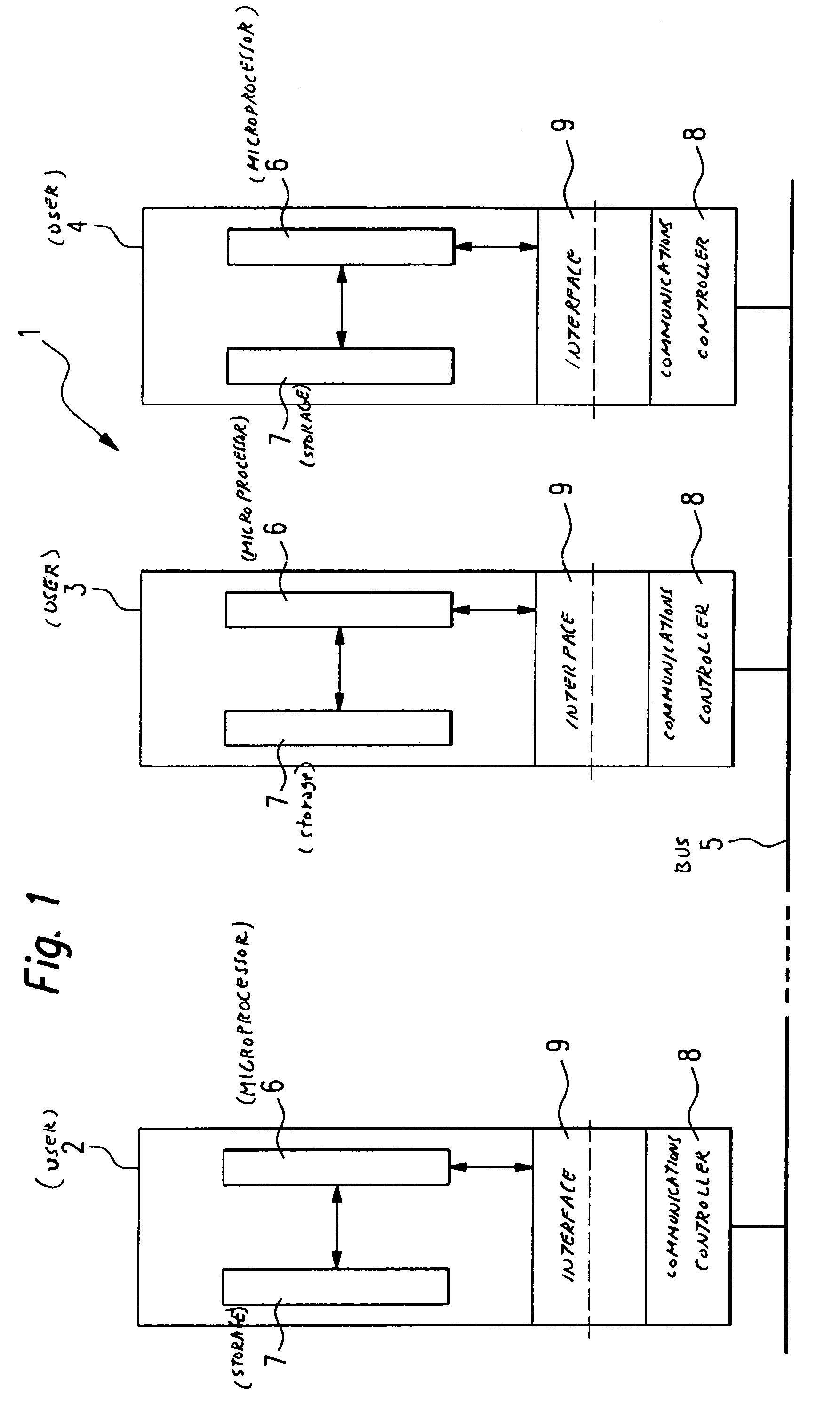
[0067]In FIG. 1, a communications system according to the present invention is designated in its entirety by reference numeral 1. The communications system 1 includes several users 2, 3, 4, which are in communication with one another, using a bus system 5 working in distributed fashion for the exchange of data. Users 2, 3, 4 are, for example, control units of a motor vehicle. The data to be exchanged are included in messages which are transmitted by users 2, 3, 4 via the bus system 5. A specifiable priority is assigned to each message.

[0068]Users 2, 3, 4 each include a computing unit (so-called process computer) which is designed as a microprocessor 6. A computer program is able to be run on microprocessor 6, and is stored in a storage element 7, e.g., a flash memory. The computer program is suitable for executing the method according to the present invention. The computer program is loaded into microprocessor 6 before or during processing. Users 2, 3, 4 also include a communication...


PUM


Abstract

The present invention provides a method and a communications system for the exchange of data between at least two users who are in contact with one another using a bus system. The data are included in messages which are transmitted by users over the bus system. A specifiable priority is assigned to each message. In order to achieve, in the normal case, a high probability of a short latency period (t) of a message to be transmitted, and to be able to guarantee, in the worst case, a maximum latency period (tmax), it is provided that the priorities assigned to the messages be dynamically modified during the operation of bus system. Preferably, the set of all messages is subdivided into equivalence classes, and a priority is assigned to each equivalence class. During the operation of the bus system, the priorities of the messages are dynamically modified within an equivalence class, and the priorities of the equivalence classes are dynamically modified.

Description

FIELD OF THE INVENTION[0001]The present invention relates to a method and a communications system for the exchange of data among at least two users who are in contact with one another via a bus system, wherein the data are included in messages which are transmitted by the users via the bus system, and a specifiable priority is assigned to each message. The present invention also relates to a bus system for the exchange of data among at least two users of a communications system. In addition, the present invention relates to a storage element for a user, e.g., a control unit, of a communications system, which is in contact with at least one additional user for the exchange of data via a bus system, which storage element stores a computer program which is executable on a computing element of the user.BACKGROUND OF THE INVENTION[0002]The networking of control units, sensors and actuators using a communications system has increased greatly in recent years in motor vehicle manufacturing....

Claims


Application Information

Patent Timeline
Patent Type & Authority Patents(United States)
IPC IPC(8): G06F15/16G06F13/42
CPCG06F13/4217
Inventor FUEHRER, THOMASMUELLER, BERND
Owner ROBERT BOSCH GMBH
Why Eureka
Try Eureka