Traffic shaping circuit, terminal device and network node

a traffic shaping circuit and terminal device technology, applied in data switching networks, frequency-division multiplexes, instruments, etc., can solve the problems of difficult to selectively provide priority control over packets which need to be transferred with low latency in the contracted bandwidth, and to achieve the effect of suppressing the increase of a latency period

Active Publication Date: 2011-12-06
ALAXALA NETWORKS
View PDF15 Cites 0 Cited by
  • Summary
  • Abstract
  • Description
  • Claims
  • Application Information

AI Technical Summary

Benefits of technology

[0010]The hierarchical shaping model (Background Art 3) has a contract sorting portion and a priority sorting portion so that the hierarchical shaping model can perform priority control by classifying packets from a user into queues in accordance with priorities in a contracted bandwidth, while complying with the contracted bandwidth of the same user with the network. In this manner, low latency transfer of low latency packets can be implemented.
[0017]In this manner, priority transfer control in each contracted bandwidth (VLL) can be achieved. Since the bandwidth in each class is controlled while priority is given to comply with the contracted bandwidth of each user, it is difficult to shorten a latency period depending on the transfer time of each contracted bandwidth (each VLL). When, for example, there are transmission packets in a queue of a specific user, low latency packets for the specific user may need to wait for transmission timing unless the bandwidths allocated to the other users are consumed. Thus, a latency period depending on the allocated bandwidth may increase. In the case where, for example, there is a request for transmitting low latency transfer class packets at the time when the VLL (0) has consumed the allocated bandwidth, the low latency transfer class packets can just wait because the bandwidth needs to be complied with even if there are low priority WFQ packets in the queues of the other users (VLL (1, 2)).
[0022]To summarize the abovementioned problems, there is a demand for a traffic shaping device in each of a packet transmission terminal and a packet switch, which complies with a contracted bandwidth, and at the same time, which minimizes a latency period for a low latency transfer class in the case where priority is given to comply with the contracted bandwidth.
[0023]In consideration of the abovementioned circumstances, an object of the present invention is to provide a traffic shaping circuit, a transmission terminal and a network node for transferring a low latency packet of a specific user with priority so as to suppress increase of a latency period while complying with contracted bandwidths of bandwidth contract parties (such as users) respectively in the case where the users share a bandwidth of one and the same medium (which can be a shared wireless bandwidth such as an Ethernet line or a wireless LAN) for transferring packets.
[0071]According to the invention, it is possible to provide a traffic shaping circuit for transferring a low latency packet of a specific user with priority so as to suppress increase of a latency period while complying with contracted bandwidths of bandwidth contract parties (such as users) respectively in the case where the users share a bandwidth of one and the same medium (which can be a shared wireless bandwidth such as an Ethernet line or a wireless LAN) for transferring packets.

Problems solved by technology

It was however difficult to offer fair bandwidth service based on contracted bandwidths among contract parties (users) (Background Art 1).
Although it is possible to use the bandwidth control model to offer bandwidth provision service, i.e. SLA (Service Level Agreement) management service for sharing one and the same line bandwidth among contract parties (users) each consequently using a contracted bandwidth (logical bandwidth), it was difficult to selectively provide priority control over packets which needs to be transferred with low latency in the contracted bandwidth (Background Art 2).

Method used


Image

  • Traffic shaping circuit, terminal device and network node
  • Traffic shaping circuit, terminal device and network node
  • Traffic shaping circuit, terminal device and network node

Examples


embodiment 1

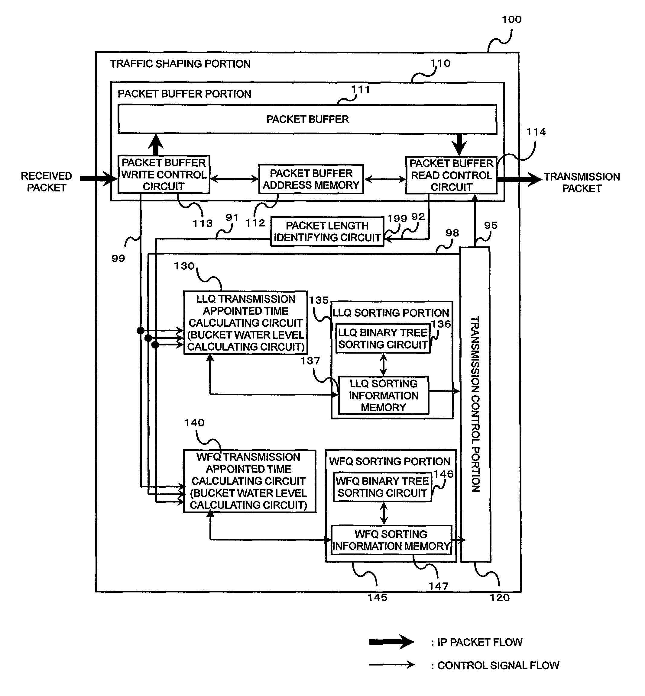
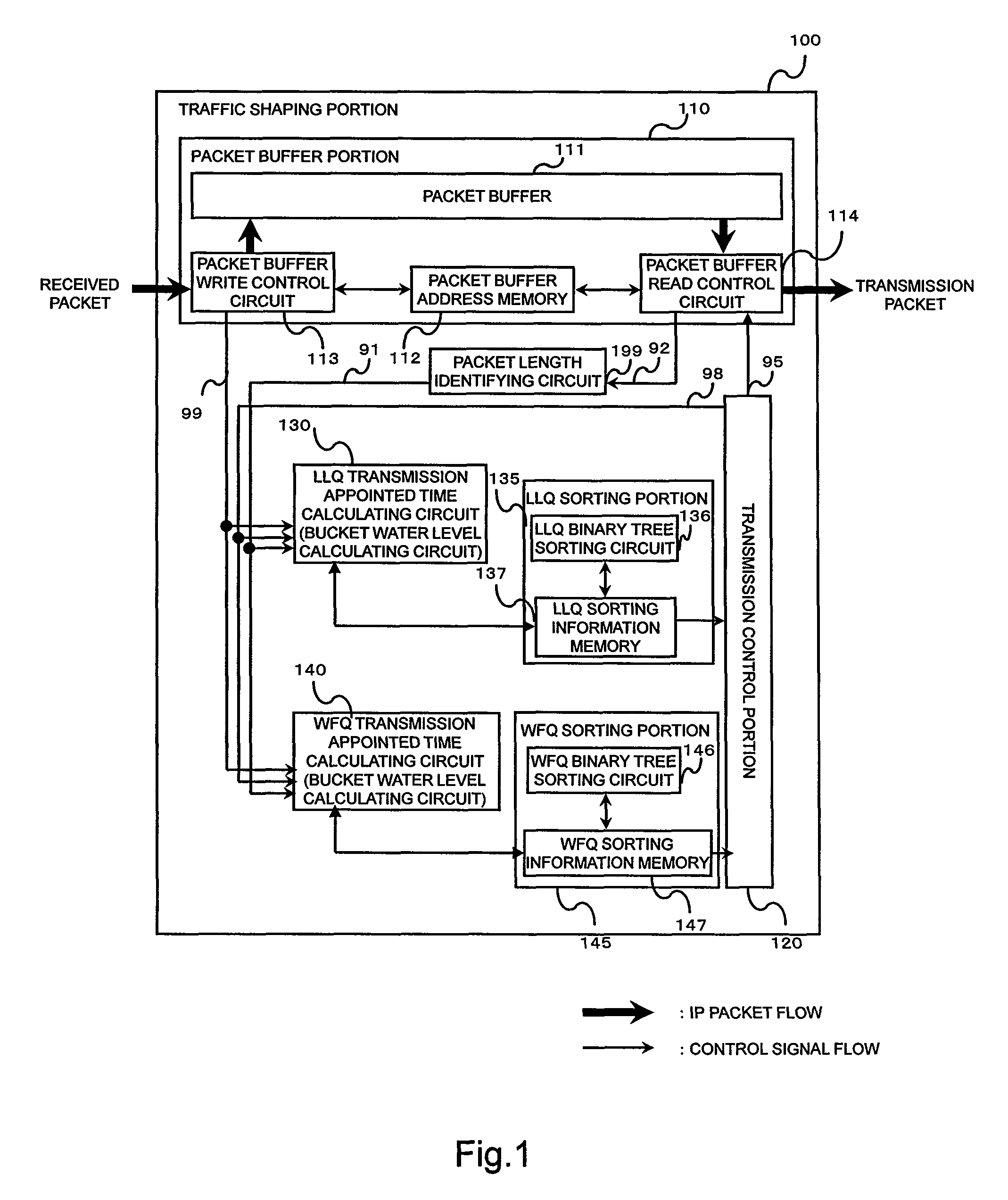
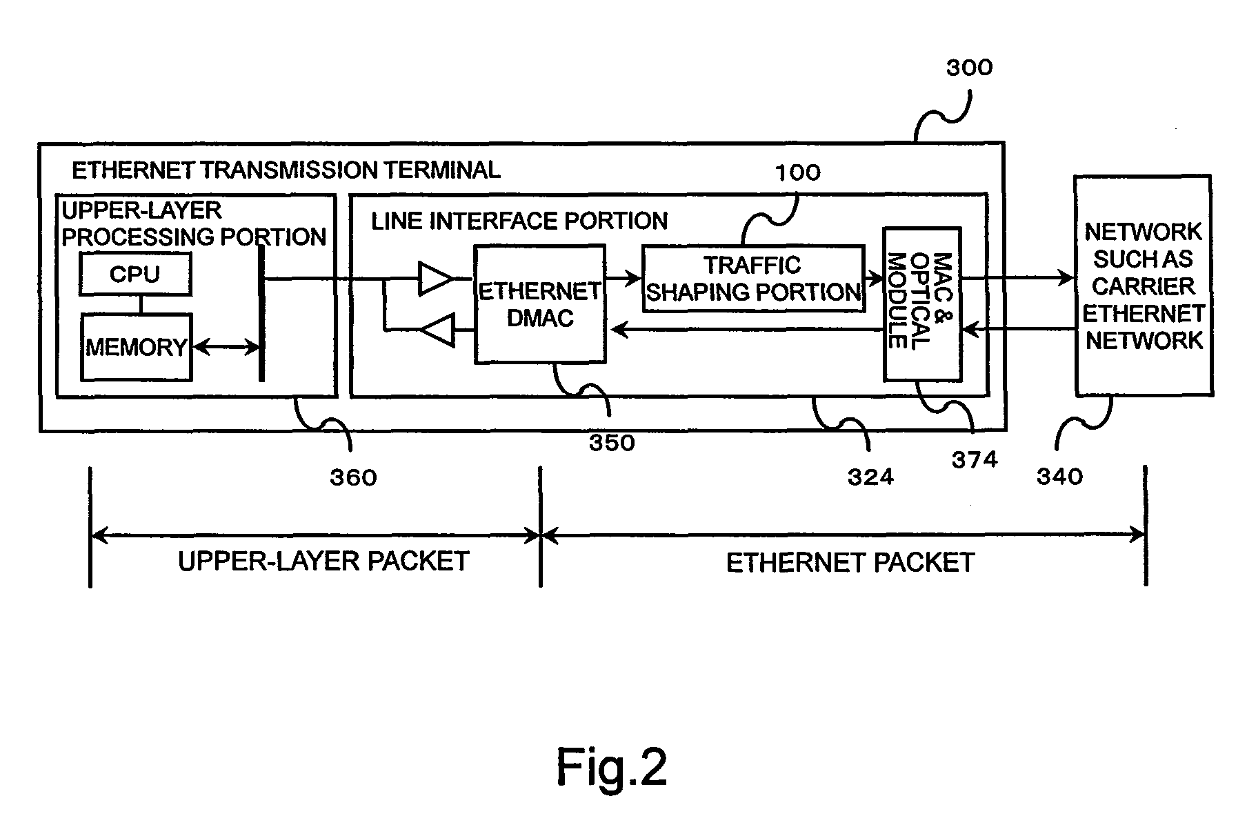
[0087]An example in which a traffic shaping device is applied to the terminal 300 shown in FIG. 2 will be described in detail hereinafter as a mode for carrying out the invention. The Ethernet transmission terminal implements VLL shaping and priority control synchronously in the traffic shaping device. There is assumed the case where, for example, two classes, i.e. an LLQ (k) (first priority class, first queue) and a WFQ (k) (second priority class, second queue) are provided in a VLL (k) (virtual connection) so that priority control between the classes is performed (Embodiment 1).

[0088]As described above, the VLL, LLQ and WFQ are concepts of virtual logical bandwidths in a packet switching network using bandwidth control, and do not depend on any specific protocol. Accordingly, the mode for carrying out the invention can be also applied to Ethernet packet, IP packet, MPLS (Multi-Protocol Label Switching) packet, and ATM cell. MPLS shim label, IP packet header, and VLAN-tag (Virtual ...

embodiment 2

[0136]The case where the traffic shaping device according to the mode for carrying out the invention is applied to an Ethernet transmission terminal has been described in the aforementioned example. As described above, the traffic shaping device may be installed in any important point in a network such as a relay node from a private network to a public network, in addition to the Ethernet transmission terminal (Embodiment 2).

[0137]FIG. 9 shows a configuration diagram in which the traffic shaping device according to the mode for carrying out the invention is applied to an Ethernet switch 301 connected to a carrier Ethernet network 340.

[0138]For example, the Ethernet switch 301 has line interface portions 320 and 321 to Ethernet terminals 330 and 331, a switch portion 310, and a line interface portion 325 to the carrier Ethernet network 340. The line interface portion 325 has a traffic shaping portion 100 corresponding to the carrier Ethernet network and an MAC & optical module 375.

[0...

embodiment 3

[0140]A trunk-type traffic shaping device in which traffic shaping of lines is performed by one traffic shaping device will be described as another example of the mode for carrying out the invention (Embodiment 3).

[0141]FIG. 10 shows an example in which an Ethernet switch is formed as the trunk-type traffic shaping device.

[0142]Packet flows generated by terminals 332 and 333 are inputted to a switch portion 311 through line interface portions 322 and 323 of an Ethernet switch 302. Also when one of output lines has been decided by the switch portion 311, each packet is temporarily transferred to a traffic shaping portion 101. Operations the same as the various processes (such as VLL sorting) of the traffic shaping portion 100 according to Embodiment 1 are made in the traffic shaping portion 101. Each packet outputted from the traffic shaping portion 101 is transmitted through the switch portion 311 again to a carrier Ethernet network 340 from a line interface portion 326 or 327 of ea...


PUM


Abstract

In order to allow priority transfer (fluctuation) over VLL packets while keeping each contracted bandwidth constantly, a leaky bucket model is expanded to have a threshold 1509 for permitting transmission of a packet (e.g. a WFQ packet) other than an LLQ packet and a threshold 1501 (larger than the threshold 1509) for permitting transmission of the LLQ packet (two-threshold leaky bucket model). In this manner, even when a WFQ cannot be transmitted, an LLQ can be transmitted with priority. In addition, while the total bandwidth of the WFQ and LLQ, i.e. the bandwidth of the VLL contains fluctuation, the contracted bandwidth can be complied with. The circuit of the model is provided in LLQ and WFQ transmission appointed time calculating circuits so as to calculate respective transmission appointed times so that an LLQ / WFQ is selected and a packet is selected based on the times considering priority.

Description

BACKGROUND OF THE INVENTION[0001]The present invention relates to a traffic shaping circuit, a terminal device and a network node. It particularly relates to a traffic shaping circuit in a fixed- or variable-length packet transmission terminal or a network node (such as a router), the transmission terminal and the network node.[0002]There is increasing importance of a quality of service function (hereinafter referred to as QoS function) in packet communication implemented using an asynchronous transfer mode (ATM) switch, a router, etc. As typical examples of the QoS function, there are priority control (low latency period transfer), discard control (low discard rate transfer), bandwidth control (maximum or minimum bandwidth ensuring transfer), etc. Among these, the bandwidth control is a function for dividing a physical line bandwidth into logical bandwidths and transmitting / receiving packets in the divided logical bandwidths. For example, the bandwidth control is the QoS required f...

Claims


Application Information

Patent Timeline
Patent Type & Authority Patents(United States)
IPC IPC(8): H04L12/56H04L47/22H04L47/21H04L47/52H04L47/56
CPCH04L12/5693H04L47/10H04L47/215H04L47/22H04L47/2441H04L47/30H04L47/562H04L47/6215H04L47/50
Inventor AIMOTO, TAKESHI
Owner ALAXALA NETWORKS
Why Eureka
Try Eureka