Condensed retractable safety marker

a safety marker and condensed technology, applied in the field of condensed retractable safety markers, can solve the problems of inability to reuse, inability to meet the needs of use, so as to reduce the cost

Active Publication Date: 2007-08-28
TIPALDO JOHN M
View PDF13 Cites 17 Cited by
  • Summary
  • Abstract
  • Description
  • Claims
  • Application Information

AI Technical Summary

Benefits of technology

[0006]While this has long been recognized as a traffic safety problem many needless deaths and injuries continue to happen every year. Current methods of enhancing motorist awareness includes; flares, solid plastic cones and collapsible or spring cones. While all devices may accomplish the same goal as the presented invention, the presented invention is designed to help eliminate current difficulties encountered with their use. With roadside flares there is the inherent short fall that they only last a given period of time and are not reusable. In addition, they are usually only several inches above the roadway service and may present difficulty in operating. Solid plastic cones are easy to place along the roadway however unless they are properly weighted and sized they may be displaced due to strong gusts of winds. In addition, the larger the cone the more storage space that is required. This is a disadvantage (especially in small passenger vehicles) and therefore reduces their attractiveness of the use. In recent years several collapsible or spring traffic cones have been introduced into the market place. The current invention is a significant improvement to these designs since the use of the flexible hinges on the vertical risers and the use of a rotating base support allows requires approximately ½ the necessary storage space. In addition, when compared to the designs that require springs (U.S. Pat. No. 5,305,705), the present invention is totally self-contained and does not require any additional locking mechanism when storing. The reduced storage space significantly increases the attractiveness of the present invention, especially in emergency response vehicles where space is at a premium.
[0007]The present invention is a variation of my prior U.S. Pat. No. 6,508,195 in that the porous casing is replaced by a series of vertical risers. The vertical risers may be described as a rectangular or trapezoidal shaped flexible “box” where the top and bottom sides are open. The vertical risers are designed to fit within each other and are designed with flexible hinges extending its entire length on each corner so that they may store relatively flat. In U.S. Pat. No. 6,508,195 two retractable arms are used as a means of expanding the porous casing from a compact to expanded position. In the present invention, the two retractable arms are replaced by a single retractable arm placed in the center of the lower portion as is used as a means of expanding the series of vertical risers from a compact to expanded position. As in U.S. Pat. No. 6,508,195 the base supports are connected to the lower portion by a series of protruding tabs and holes. In the present invention, the lower vertical riser is connected to the base supports by a lower linkage that allows the series of vertical risers to transform from a relatively flat position is storage to a rectangular shape when the base support goes from a closed to an open position when rotated about the lower portion. In addition, the upper vertical riser is also linked to the upper portion of the retractable arm. This upper linkage allows for the vertical risers to be lifted from a compact to expanded position when the retractable arm is fully expanded. In order to help accomplish this movement the upper portion of the retractable arm contains a handle.
[0008]The Condensed Retractable Traffic Cone has been designed to be employ easily, store compactly, withstand prevailing winds and be economical.
[0009]The Condensed Retractable Traffic Cone is a combination of several pieces. The first two pieces are referenced to as the base supports. The base supports are similar in design and function to the base supports disclosed in may prior U.S. Pat. No. 6,508,195. The base supports are connected to the lower portion in a similar manner as taught in my prior U.S. Pat. No. 6,508,195. Connected to the lower portion is single retractable arm with a handle on its upper portion. When the device is fully deployed the retractable arm is perpendicular to the base supports. When the device is in storage the retractable arm is parallel to the base supports. In the present invention the porous casing taught in U.S. Pat. No. 6,508,195 is replaced by a series of vertical risers. Each vertical riser is designed with hinges along each corner that extend its entire length. This design allows for the vertical rises to be able to change shape when pressure is applied. The vertical risers are designed to fit within each other and may either be rectangular or slightly tapered. In order to reduce wind load on the sign support structure, the each vertical riser may be designed with “air-flow” holes. Also the bottom portion of the retractable arm may be designed in the shape of a spring that would allow for the slight deflection of the present invention when subject to high wind loads. Allowing for this slight deflection may reduce the overall weight of the device thereby potentially reducing its cost.
[0013]The present invention offers an improvement over the previous designs in that the base support has been designed to fold in half thereby significantly reducing the necessary storage space when compared to similar sized designs. Through the use of “hinged” vertical risers that store effectively “flat” when not in operation and then “open” when in operation, significantly also reduces the necessary storage space when compared to devices that use a rigid sleeve design. This improved storage efficiency in both the base support and the vertical risers increases the attractiveness of the present invention to the user since it requires significantly less storage space when compare to the current state of the art. This is especially essential when the users are the highway motorcycle patrol or motorcyclists in general. The present invention has been designed to fit into the side compartment of their motorcycle. This is envisioned as a primary application for the present invention.
[0015]Further, the device has been designed so that “reflective decals” can be directly affixed to the device to alert motorists. Several other designs, especially those that require the use of a spring or a coil require the use of a “flexible reflective material”. “Reflective decals” (similar to those used on existing traffic control devices) are usually brittle and would crack when stored in a compressed position, therefore they would not be recommended for many of the previously discussed prior designes. “Reflective tape” may also be used in many of the previously disclosed designed. While less brittle than “decals” they have a problem with wrinkling when compressed. A primary benefit of the use of reflective “decals” or “tape” is the reduced cost when compared to “collars” currently used on rigid traffic cones and on several existing “collapsible” devices.

Problems solved by technology

Each year hundreds of motorists are either killed or injured along side the roadway.
While this has long been recognized as a traffic safety problem many needless deaths and injuries continue to happen every year.
With roadside flares there is the inherent short fall that they only last a given period of time and are not reusable.
In addition, they are usually only several inches above the roadway service and may present difficulty in operating.
Solid plastic cones are easy to place along the roadway however unless they are properly weighted and sized they may be displaced due to strong gusts of winds.
In addition, the larger the cone the more storage space that is required.
This is a disadvantage (especially in small passenger vehicles) and therefore reduces their attractiveness of the use.
Through the use of “hinged” vertical risers that store effectively “flat” when not in operation and then “open” when in operation, significantly also reduces the necessary storage space when compared to devices that use a rigid sleeve design.
“Reflective decals” (similar to those used on existing traffic control devices) are usually brittle and would crack when stored in a compressed position, therefore they would not be recommended for many of the previously discussed prior designes.
While less brittle than “decals” they have a problem with wrinkling when compressed.

Method used


Image

  • Condensed retractable safety marker
  • Condensed retractable safety marker
  • Condensed retractable safety marker

Examples


second embodiment

[0029]the invention is illustrated in FIG. 5. As illustrated in the figure, lower, middle and upper rectangular shaped hollow vertical risers (10,6,7) may be designed with “air-flow” holes (205) as to reduce the overall wind load on the structure.

third embodiment

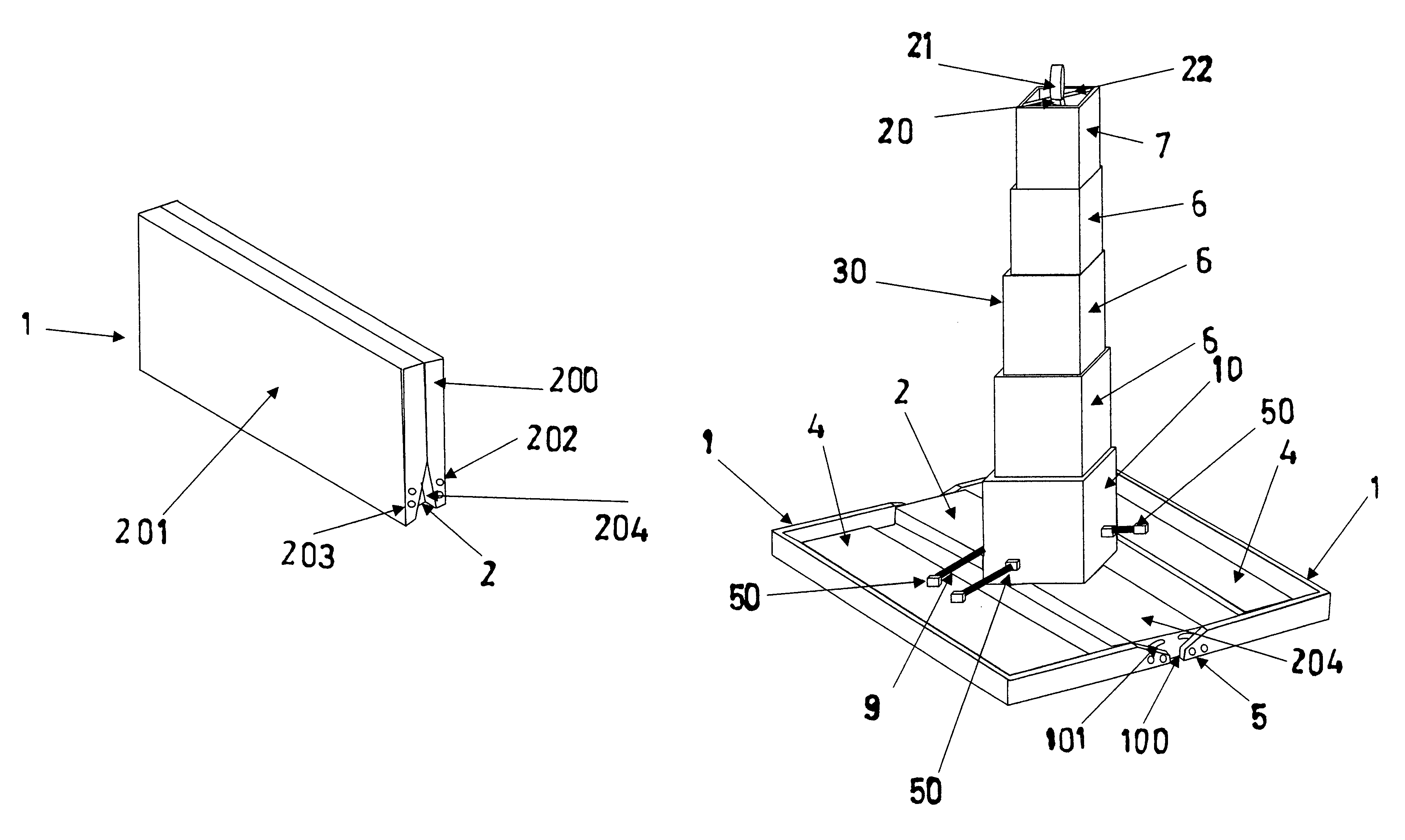
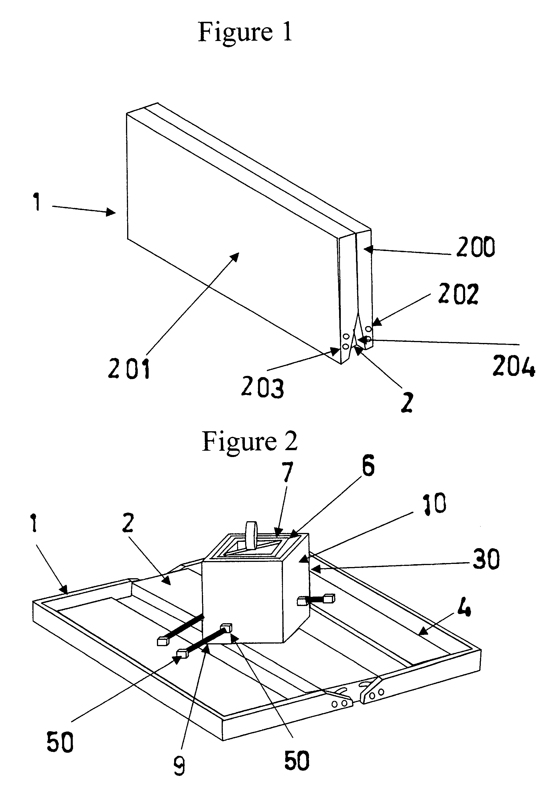
[0030]FIG. 6 illustrates the present invention, in the open and expanded position without the vertical risers and is intended to show the placement of the retractable arm (20) in relation to the base supports (1) and the lower portion (2).

fourth embodiment

[0031]the invention is illustrated in FIG. 7, the lower portion of the retractable arm (20) may be designed in the shape of a spring (60) to allow for greater flexibility of the device. This flexibility would allow for temporary slight displacement of the lower, middle and upper rectangular shaped hollow vertical risers (10,6,7) under high wind conditions, thus reducing the necessary weight of the support weights (4).

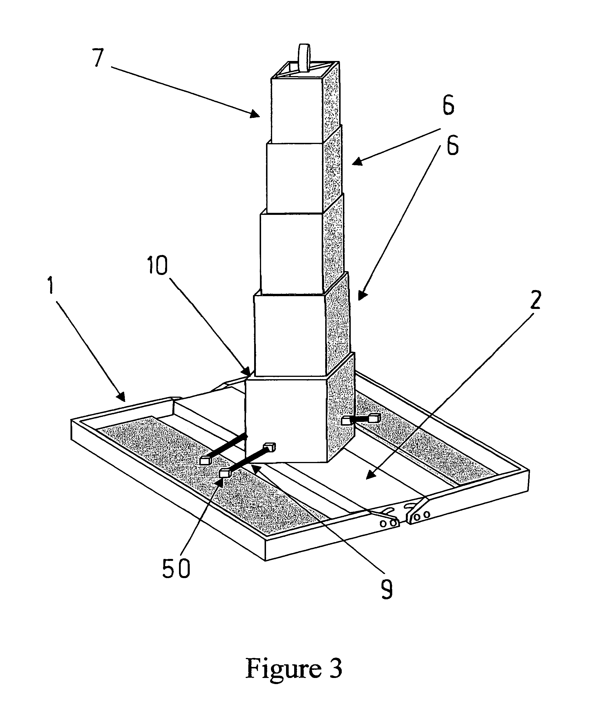
[0032]To deploy the current invention, the user simply rotates the two base supports (1) about the lower portion (2) into a locked position perpendicular to the retractable arm (20), and then lifts the lower, middle and upper rectangular shaped hollow vertical risers (10,6,7) into a locked vertical position by use of the handle (21) on the upper portion of the retractable arm (20). The device is now ready for use.


PUM


Abstract

A condensed retractable traffic cone is a device designed to provide motorists with advance warning of disabled vehicles and / or work zone areas. The device has been designed to withstand reasonable winds through the use of two base supports, a lower portion, a retractable arm and a series of retractable vertical risers. The retractable vertical risers in combination with a retractable arm allow for the device to easily expand to height consistent with traffic engineering design standards when in operation and then compact when it is in storage. The two base supports are designed not only to provide the necessary structural stability but to also open and close about the retractable vertical risers thus providing for additional compactness. The vertical risers are designed with flexible hinges so that they may store flat and expand to a rectangular shape when the base supports are rotated to an open position. This is accomplished a by linkage connecting the lower vertical riser and the base supports.

Description

BACKGROUND AND SUMMARY OF THE INVENTION[0001]This application relates to means of altering motorists to the presence of disabled vehicles or work zone areas. Each year hundreds of motorists are either killed or injured along side the roadway. Many of these accidents may be prevented if the oncoming motorist had advance warning of the presence of these disabled vehicles. The present invention is an improvement or alternative to my prior U.S. Pat. No. 6,508,195.[0002]In recent years, a variety of traffic warning devices have become known and reference may be had to the following U.S. patents for a description of these prior art of traffic warning devices; U.S. Pat. Nos. 6,508,195, 6,681,715, 2,954,005, 3,496,904, 4,006,702, 4,197,807, 4,256,50, 2,762,327, 3,132,624, 3,520,235, 4,462,145, 4,466,376, 6,971,329 B1, 6,746,337 B1, 4,806,046, 4,090,468, 3,732,842, 3,695,213, 3,520,273, 3,234,903, 3,021,755 and 5,287,822.[0003]Over the years there have been many attempts to provide a retract...

Claims


Application Information

Patent Timeline
Patent Type & Authority Patents(United States)
IPC IPC(8): E01F9/00
CPCE01F9/012E01F9/688E01F9/654
Inventor TIPALDO, JOHN M.
Owner TIPALDO JOHN M
Why Eureka
Try Eureka