LED mounting having increased heat dissipation

a technology of heat dissipation and led displays, which is applied in the direction of solid-state devices, basic electric elements, semiconductor devices, etc., can solve the problems of high cost relatively expensive use of metal core pcbs, and achieve the effect of increasing the heat dissipation of led displays

Active Publication Date: 2007-08-28
DOCUMENT SECURITY SYST
View PDF14 Cites 43 Cited by
  • Summary
  • Abstract
  • Description
  • Claims
  • Application Information

AI Technical Summary

Benefits of technology

[0003]There is disclosed a system and method for increasing heat dissipation of LED displays by using the current PCB packaging mounted to a LCD panel support structure thereby eliminating the need for a metal core PCB. In one embodiment, reverse mounted LEDs having heat dissipation pads are used to optimize heat transfer to a metal layer which is then placed in contact with the LCD support structure.

Problems solved by technology

Using metal core PCBs is relatively expensive since the cost of the material for a metal core PCB is high.

Method used


Image

  • LED mounting having increased heat dissipation
  • LED mounting having increased heat dissipation
  • LED mounting having increased heat dissipation

Examples


Embodiment Construction

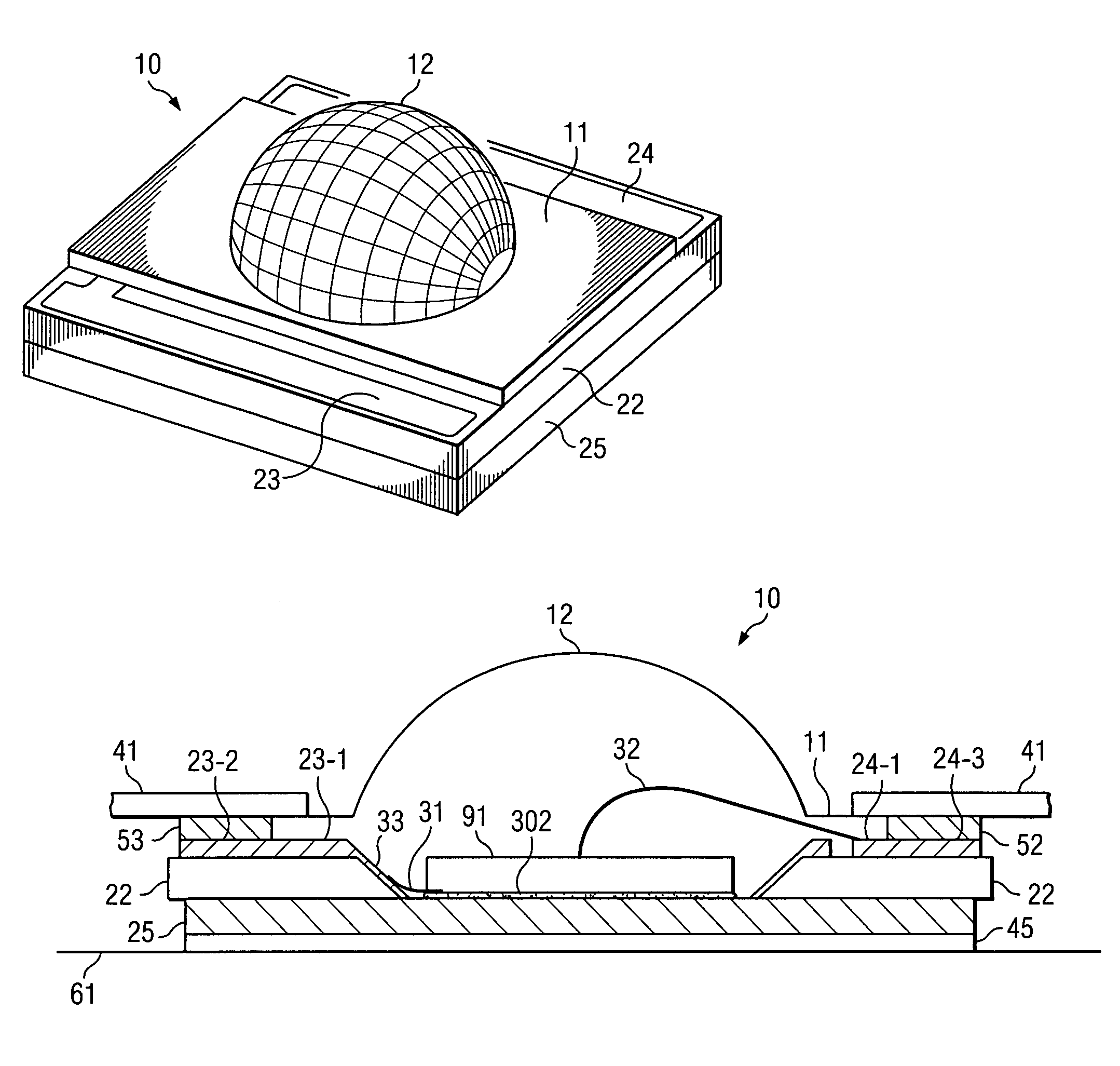
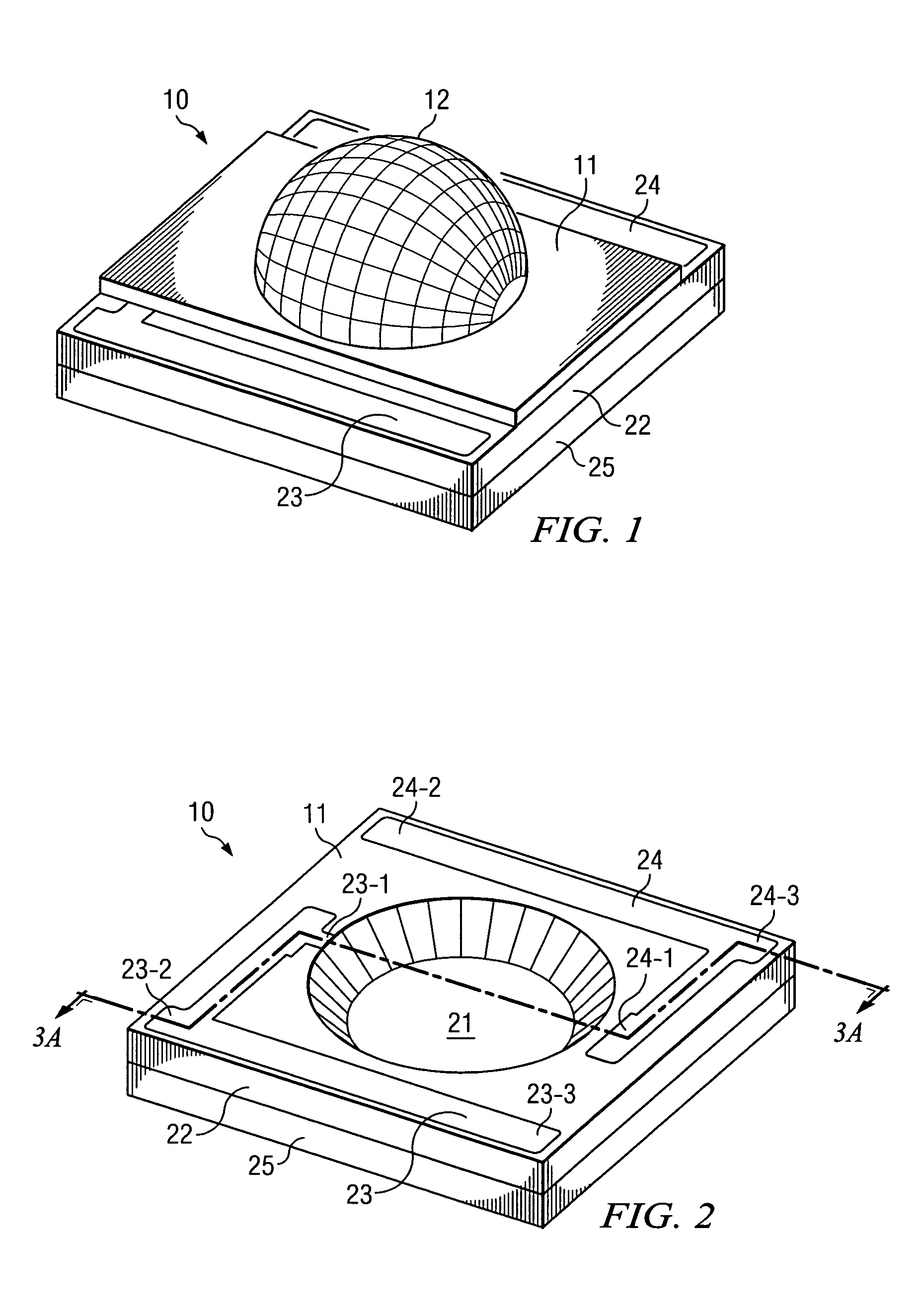
[0010]FIG. 1 shows a perspective view of one embodiment of single LED package 10 consisting of PCB substrate 22 mated to heat-sink pad 25. Optical dome 12 is constructed, by molding or otherwise, above surface 11 which in turn is mated to substrate 22. Contact strips 23 and 24 are constructed on the surface of substrate 22 and are used as discussed in more detail hereinafter.

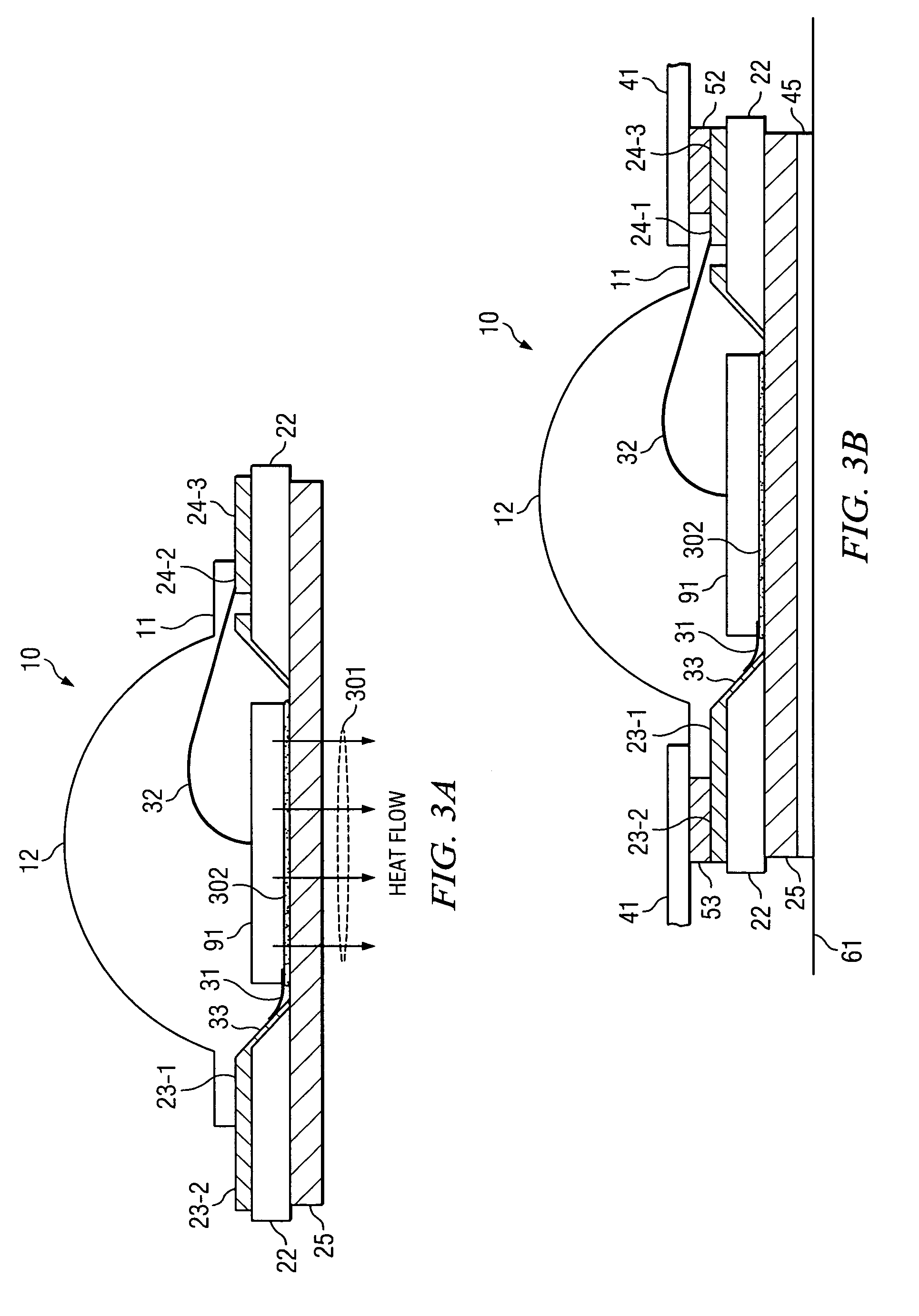
[0011]FIG. 2 shows package 10 with the LED and optical dome 12 removed. An LED chip (or other light emitting source) would be physically attached to heat-sink pad 25 inside reflector cup 21 by a terminally conductive bonding agent, or by other fastener means. The LED would then be wire bond connected to pads 23-1 and 24-1 of contact strips 23 and 24, respectively, for subsequent connection to an external electrical path. The heat path from the LED is through heat-sink pad 25 which can be, for example, copper. Note that the heat path from the LED is pad 25 and is separate from the electrical path to optimize the ...


PUM


Abstract

There is disclosed a system and method for increasing heat dissipation of LED displays by using the current PCB packaging mounted to a LCD panel support structure thereby eliminating the need for a metal core PCB. In one embodiment, reverse mounted LEDs having heat dissipation pads are used to optimize heat transfer to a metal layer which is then placed in contact with the LCD support structure.

Description

BACKGROUND OF THE INVENTION[0001]The need for LEDs having high power (increased brightness) is increasing. As power increases, so does the need for heat dissipation since if the heat generated by the LED junction is not dissipated effectively the brightness of the LED is diminished.[0002]Currently LEDs are produced in surface-mounted LED packages which are mounted to aluminum metal core PCBs. The metal core PCBs act as direct heat-sinks drawing the heat away from the LEDs. Using metal core PCBs is relatively expensive since the cost of the material for a metal core PCB is high.BRIEF SUMMARY OF THE INVENTION[0003]There is disclosed a system and method for increasing heat dissipation of LED displays by using the current PCB packaging mounted to a LCD panel support structure thereby eliminating the need for a metal core PCB. In one embodiment, reverse mounted LEDs having heat dissipation pads are used to optimize heat transfer to a metal layer which is then placed in contact with the L...

Claims


Application Information

Patent Timeline
Patent Type & Authority Patents(United States)
IPC IPC(8): H01L29/22H01L33/54H01L33/64
CPCH01L33/647H01L33/54H01L33/642H01L2224/48091H01L2924/00014H01L2224/73265H01L25/0753H01L27/156H01L33/64A47J43/28A47J45/06
Inventor MOK, THYE LINNTAN, SIEW KIMNG, SHIN WEN
Owner DOCUMENT SECURITY SYST
Why Eureka
Try Eureka