Imaging tomography apparatus with two acquisition systems, and method for determining their system angles

a tomography and imaging technology, applied in tomography, material analysis using wave/particle radiation, instruments, etc., can solve problems such as general worsening of the achievable image quality

Inactive Publication Date: 2007-08-28
SIEMENS HEALTHCARE GMBH
View PDF11 Cites 30 Cited by
  • Summary
  • Abstract
  • Description
  • Claims
  • Application Information

AI Technical Summary

Benefits of technology

[0008]An object of the present invention is to provide an imaging tomography apparatus and method of the type initially described, wherein system angles of the acquisition systems disposed in the azimuthal direction around a common rotational axis can be determined in a simple manner for various rotation angle speeds.
[0011]An improvement of the slice or volume images generated from the detector output signals is possible by the inventive determination of system angles, by allowing the exactly-determined system angles to be used for the reconstruction. Artifacts in the slice or volume image due to incorrect underlying system angles of the acquisition systems in the reconstruction are prevented in this manner.
[0015]So that the mapping of the reference object on the detectors of both acquisition systems is independent of the rotation angle positions of the acquisition systems and so that a simple evaluation of the detector output signals is possible, the reference object exhibits a rotationally symmetrical design.
[0016]The calculation of the measurement value associated with a detector or of the position of the reference object that can be mapped on the detector, is possible in a particularly robust manner without the influence of noise in the detector output signals, when the reference object is imaged on a number of detector elements. The position is advantageously determined from the detector output signals in the sense of an intensity focal point.

Problems solved by technology

The deviation between the desired value taken into account in the reconstruction of a slice or volume image and the actual existing system angle causes image errors (artifacts) in the reconstructed image, and thus leads to a general worsening of the achievable image quality.

Method used


Image

  • Imaging tomography apparatus with two acquisition systems, and method for determining their system angles
  • Imaging tomography apparatus with two acquisition systems, and method for determining their system angles
  • Imaging tomography apparatus with two acquisition systems, and method for determining their system angles

Examples


Embodiment Construction

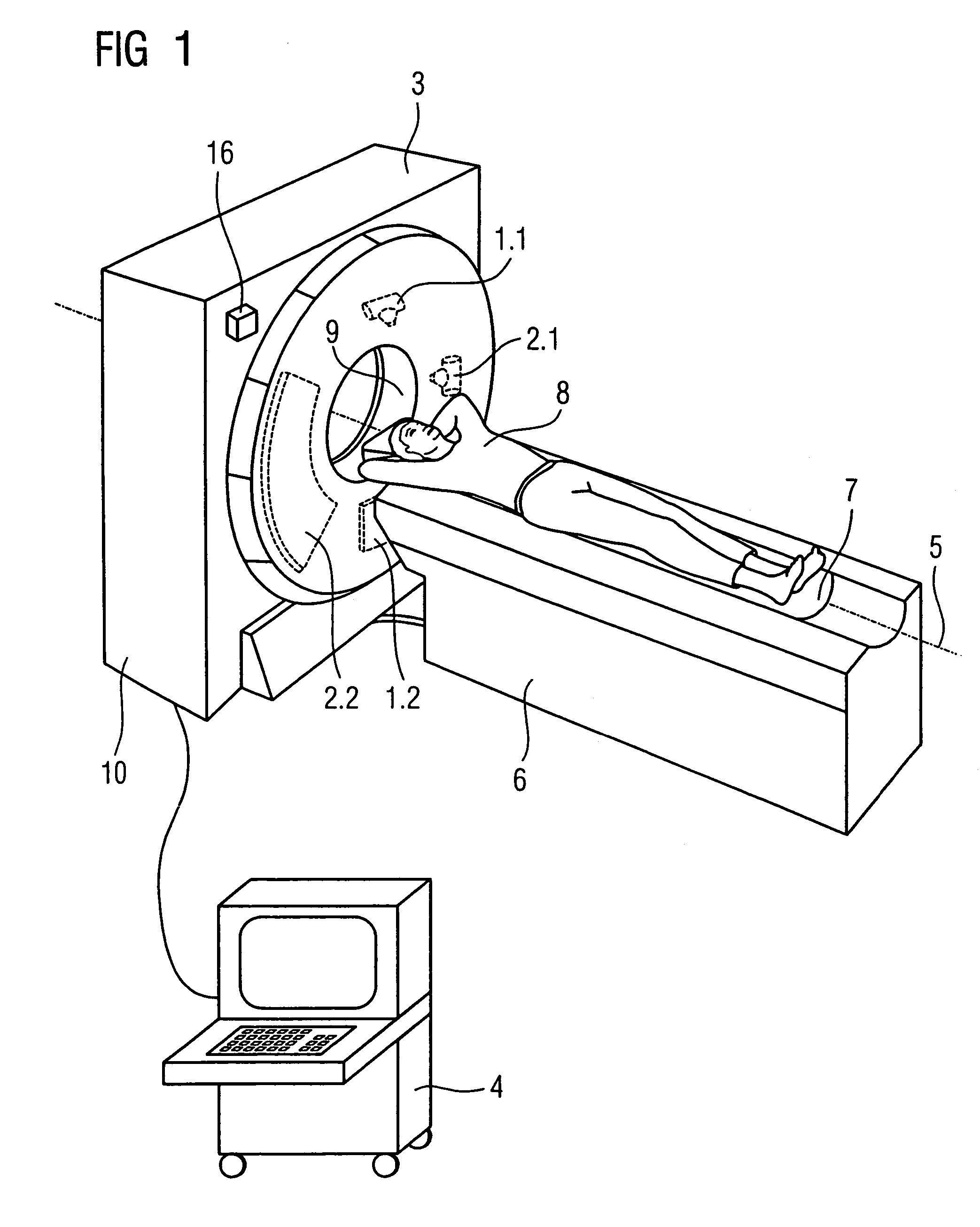
[0024]FIG. 1 shows an inventive tomography apparatus 3, here in the form of an x-ray computed tomography apparatus, with a patient bed 6 for acceptance and support of a patient 8. The patient bed 6 has a movable table plate 7 by means of which the patient 8 can be moved through an opening 9 in the housing 10 of the tomography apparatus 3 into the examination or scan region. Moreover, a continuous axial feed of the table plate 7 is effected during a spiral scan.

[0025]A gantry (not visible in FIG. 1), that can be rotated with a high speed around a rotation axis 5 running through the patient 8, is located within the tomography apparatus 3.

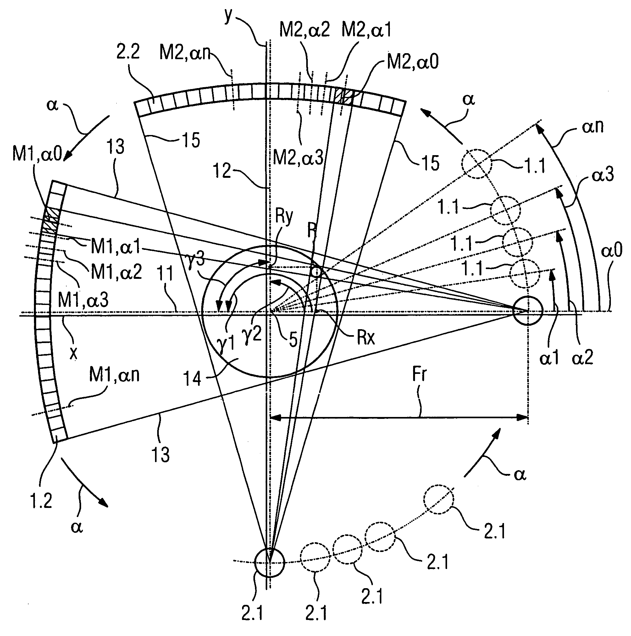
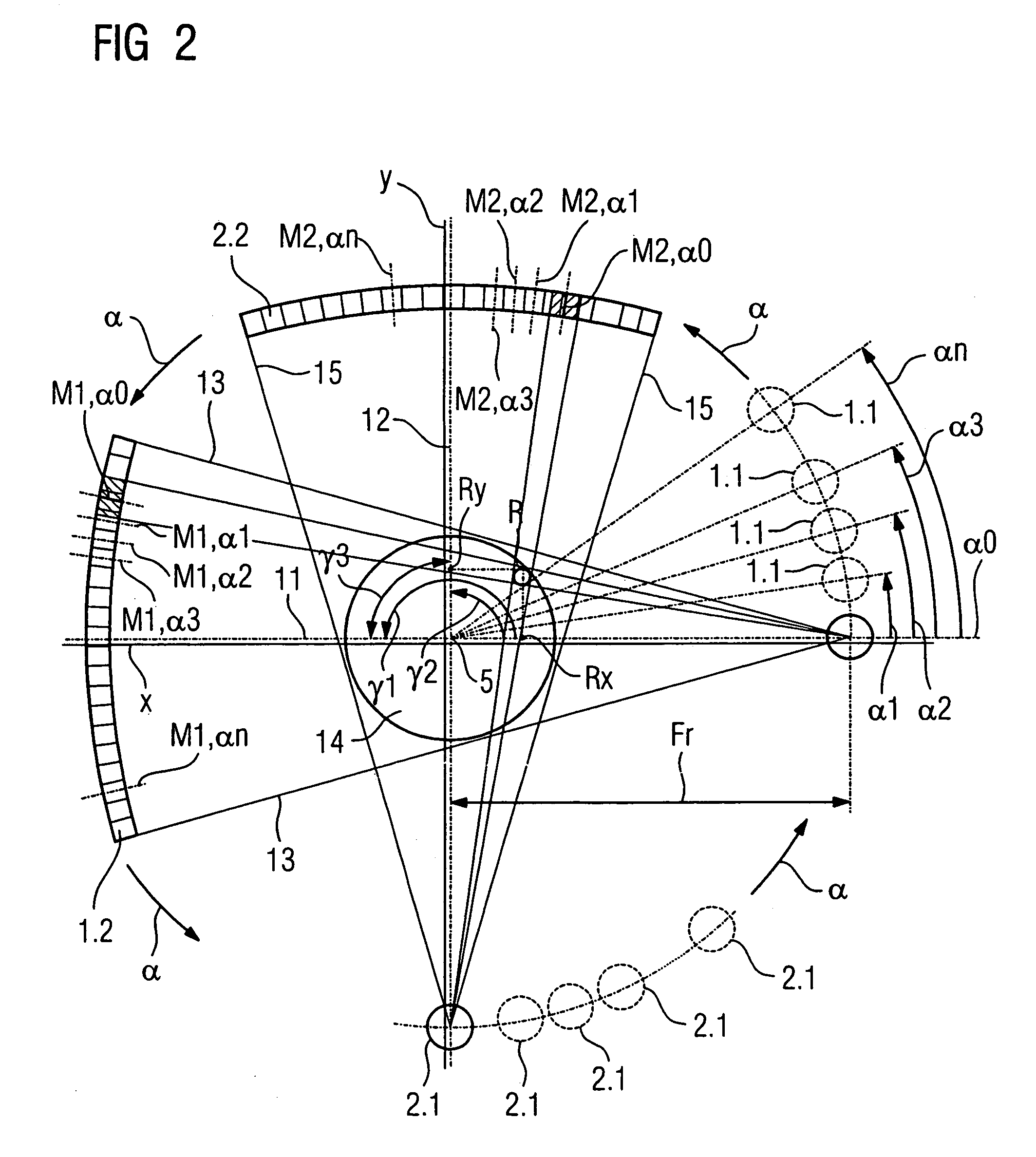
[0026]Two acquisition systems are arranged on the gantry in a predetermined manner to achieve a high scanning speed or a high scan resolution. In the exemplary embodiment, the first acquisition system has an x-ray tube as a first radiator 1.1 and, for example, an eight-row x-ray detector array as a first detector 1.2. In the exemplary embodiment, the ...


PUM

PropertyMeasurementUnit
imaging tomographyaaaaaaaaaa
rotation angle speedaaaaaaaaaa
system angleaaaaaaaaaa

Abstract

In a tomography apparatus and operating method, at least two acquisition systems are respectively each disposed in the azimuthal direction at respective specific system angles around a common rotation axis. Both system angles can be determined for a substantially constant rotation angle speed of the two acquisition systems on the basis of measurement values, which are calculated at a rotation angle position of a reference object that can be introduced into both measurement planes. The tomography apparatus in this manner enables artifact-free reconstruction of a slice or volume image using the system angles determined in this manner.

Description

BACKGROUND OF THE INVENTION[0001]1. Field of the Invention[0002]The present invention concerns an imaging tomography apparatus of the type having a first acquisition system with a first radiator and a first detector for generation of detector output signals that are a measure of the absorption of the radiation emanating from the first radiator and passing through a measurement region, and a second acquisition system with a second radiator and a second detector for generation of detector output signals that are a measure for the absorption of the radiation emanating from the second radiator, wherein, in the azimuthal direction, the first acquisition system is disposed at a first system angle and the second acquisition system is disposed at a second system, angle such that they can rotate around a common rotational axis. The invention moreover concerns a method for such a tomography apparatus for determination of the system angle of both acquisition systems.[0003]2. Description of the...

Claims


Application Information

Patent Timeline
Patent Type & Authority Patents(United States)
IPC IPC(8): G01N23/083A61B6/03
CPCA61B6/032A61B6/4014
Inventor BRUDER, HERBERTPETERSILKA, MARTINSTIERSTORFER, KARL
Owner SIEMENS HEALTHCARE GMBH
Why Eureka
Try Eureka