
Method for switching from a first operating condition of an integrated circuit to a second operating condition of the integrated circuit

a technology of integrated circuit and operating condition, which is applied in the direction of noise figure or signal-to-noise ratio measurement, pulse technique, instruments, etc., can solve the problems of consuming power of comparator, requiring greater outlay, and inability to make available the full voltage range, etc., to achieve the effect of reducing or avoiding these difficulties

Inactive Publication Date: 2003-01-16
INFINEON TECH AG
View PDF0 Cites 18 Cited by
  • Summary
  • Abstract
  • Description
  • Claims
  • Application Information

AI Technical Summary

Benefits of technology

[0007] The present invention is therefore based on the object of offering a method for switching between two different operating conditions of an integrated circuit that largely reduces or avoids these difficulties.
[0015] The inventive method and / or the inventive integrated circuit have the advantage that the switching from one operating condition into another operating condition of the integrated circuit can be implemented in a very simple way but with a high immunity to interference. As needed, the switching can be very easily initiated because the only thing needed for this is the application of a voltage level that is already available in the system to an output of the integrated circuit. Furthermore, the selection of a circuit output assures with a high certainty that the switching condition will not accidentally occur, since this is largely precluded by the usual, external interconnection of a circuit output. At the same time, the evaluation of the voltage adjacent at the circuit output can be implemented with a relatively simple circuit-oriented mechanism and can be implemented in a largely low-power or power-free manner.
[0016] According to a preferred embodiment of the inventive method, the prescribed output voltage corresponds to a logical value and the voltage externally applied to the circuit output corresponds to the logical value complementary to said logical value. This embodiment has the advantage that the evaluation of the voltage adjacent at the circuit output can be implemented nearly power-free with especially simple evaluation units, particularly logical operations. It is particularly preferred when the logical value that corresponds to the voltage adjacent at the circuit output is logically operated with the logical value that corresponds to the prescribed output voltage using an XOR operation or using a NOR operation.
[0017] According to another preferred embodiment of the inventive method, the integrated circuit is placed into the second operating condition when the voltage adjacent at the circuit output does not coincide with the prescribed output voltage over a prescribed time span. This prescribed time span has the function of internally declaring the switching valid only after this condition has existed for a certain length of time, which further enhances the immunity to interference.
[0021] According to another preferred embodiment of the inventive integrated circuit, the circuit arrangement for the switching comprises at least one time-counter unit. Such a time-counter unit can assist in implementing a prescribed time span over which the voltage at the circuit output must not coincide with the prescribed output voltage so that a switching can ensue.

Problems solved by technology

However, this solution is disadvantageous in that the full range of voltage cannot be made available for operation; furthermore, the comparator consumes power.
The realization and communication of this protocol, however, requires greater outlay, and also requires additional power consumption.

Method used


Image

  • Method for switching from a first operating condition of an integrated circuit to a second operating condition of the integrated circuit
  • Method for switching from a first operating condition of an integrated circuit to a second operating condition of the integrated circuit
  • Method for switching from a first operating condition of an integrated circuit to a second operating condition of the integrated circuit

Examples


first embodiment

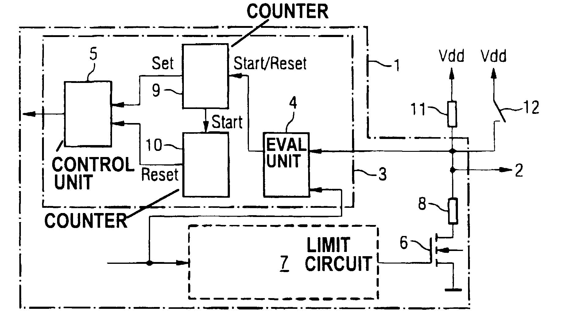
[0027] FIG. 1 shows the inventive integrated circuit 1. This integrated circuit can fulfill a number of functions. In the present example, the integrated circuit corresponds to an integrated sensor, for example, an integrated magnetic field sensor as disclosed in German patent applications 101 17 382.2, 101 17 383.0 or 101 17 384.9, whose contents are herewith incorporated by reference. Such an integrated sensor usually has at least three essential operating conditions. On the one hand, this is a type of "raw condition" in which the sensor can still be configured. In this condition, the sensor can already work normally but the sensor can be switched from operating condition into a further, second operating condition.

[0028] This second operating condition makes it possible to load specific parameter sets and to observe specific internal events. The operator of the sensor can thus optimally adapt the sensor to the respective measurement task and permanently program the optimum operati...

second embodiment

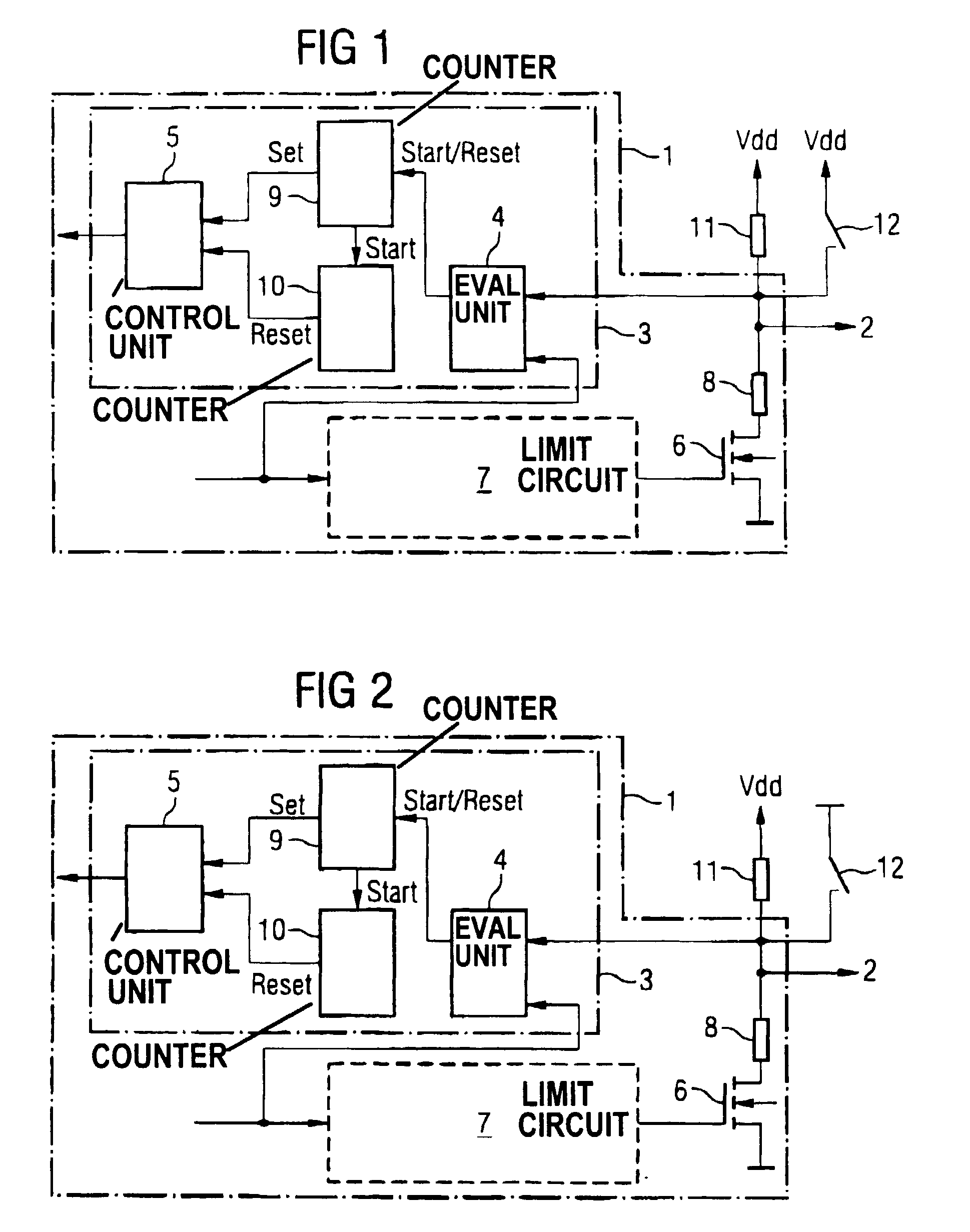
[0037] FIG. 2 shows a second embodiment of the inventive integrated circuit. This second embodiment of the inventive integrated circuit corresponds to the first embodiment of the inventive integrated circuit as described above, except for the following differences.

[0038] In this second embodiment, the first operating condition is designed such that a high level is generated at the circuit output 2 as an output signal. Accordingly, the open-drain output transistor 6 is inhibited. Instead of comprising an AND gate, this embodiment comprises a NOR gate as an evaluation unit 4.

[0039] When the user wishes to switch the integrated circuit 1 into the second operating condition, a low level is externally applied to the circuit output 2. This is indicated in FIG. 2 in that the user connects to circuit output 2 to ground by closing the switch 12. The evaluation unit 4 now queries the condition that the open-drain output transistor 6 is inhibited and that the voltage at the circuit output 2 li...

third embodiment

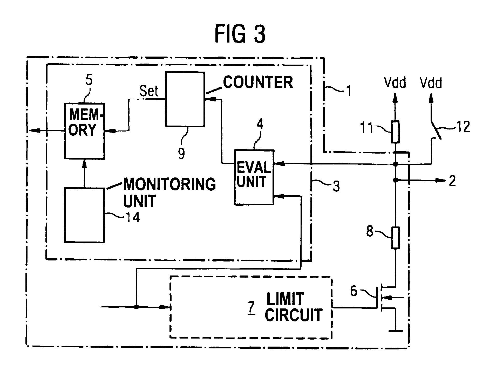
[0040] FIG. 3 shows a further embodiment of the inventive integrated circuit. This third embodiment of the inventive integrated circuit corresponds to the first embodiment of the inventive integrated circuit described above, except for the following differences.

[0041] Instead of the counter 10, the embodiment of the integrated circuit shown in FIG. 3 has a monitoring unit 14. The monitoring unit 14 serves the purpose of checking at least one criterion on whose basis a decision is made as to whether the integrated circuit is reset into the first operating condition or is placed into a further operating condition. For example, the integrated circuit can in turn be reset after the application of the operating voltage. Further possibilities include introducing a separate reset command or to utilize other, inherently forbidden conditions such as over-voltages and under-voltages for this.

[0042] The inventive method or the inventive integrated circuit have the advantage that the switching ...


PUM


Abstract

The invention provides a method for switching from a first operating condition of an integrated circuit to a second operating condition of the integrated circuit differing from the first operating condition. To that end, the output signal generated at a circuit output is externally overwritten. The inventive method or the inventive integrated circuit have the advantage that the switching from one operating condition into another operating condition of the integrated circuit can be implemented in a very simple way but with a high immunity to interference. The switching can be very easily initiated as needed because the only thing needed is the application of a voltage level--which is already available in the system--to an output of the integrated circuit. Furthermore, the selection of a circuit output assures that there is a high certainty that the switching condition will not accidentally occur because this is largely precluded by the standard and usually prescribed external interconnection of a circuit output.

Description

BACKGROUND OF THE INVENTION[0001] 1. Field of the Invention[0002] The present invention is directed to a method for switching from a first operating condition of an integrated circuit to a second operating condition of the integrated circuit differing from the first operating condition, particularly with respect to an integrated sensor.[0003] 2. Description of the Related Art[0004] Many integrated circuits implement a specific operating condition / behavior (a "test mode") for better testability; this behavior allows conclusions to be made about functions of the circuit that are difficult to measure from the outside. In order to avoid using a separate signal input for the transmission of the test mode information, but while managing with existing terminals already occupied with functions, a way must be found to make a specific signal or a combination of a plurality of signals available to the integrated circuit such that they differ from those of the normal operating case.[0005] A fun...

Claims


Application Information

Patent Timeline
IPC IPC(8): G01R31/317
CPCG01R31/31701
Inventor ALTRICHTER, HANSDRAXELMAYR, DIETERMOTZ, MARIO
Owner INFINEON TECH AG
Learn More