
Protective Sensor System for a Hand-Held Power Tool

a technology of protection sensor and hand-held power tool, which is applied in the direction of manufacturing tools, portable power-driven tools, mechanical devices, etc., can solve the problems of user touching the tool region, user may be seriously injured, and the risk of injury is considerable, so as to increase the chance of accidents.

Inactive Publication Date: 2013-05-23
ROBERT BOSCH GMBH
View PDF2 Cites 20 Cited by
  • Summary
  • Abstract
  • Description
  • Claims
  • Application Information

AI Technical Summary

Benefits of technology

The patent describes a hand-held power tool with a protective sensor unit that automatically disconnects the drive unit when a user's body part touches a dangerous region of the tool. This prevents injury and reduces the potential for injury when using hand-controlled ultrasound tools. The protective sensor unit can also be set to disconnect the drive unit when a certain contact strength is reached, reducing unintentional disconnection but ensuring operational safety of the user.

Problems solved by technology

The hand-controlled power tools under consideration here can generally be controlled with one hand, and there is therefore a risk of the user touching the tool region, in particular a sonotrode, which is designed in the form of a blade, for example, of an ultrasound-operated machine tool, with his free hand, and there is therefore a considerable risk of injury.
Since the abovementioned protective mechanisms cannot be used in hand-controlled ultrasound-operated machine tools of this kind and a user generally guides a workpiece, which is to be processed, with one hand and controls the tool with the other hand, the user may, under unfavorable conditions, for example if said user slips or is accidently pushed, unintentionally touch the active sonotrode, as a result of which the user may be seriously injured.
However, a very high level of outlay on circuitry is required.

Method used


Image

  • Protective Sensor System for a Hand-Held Power Tool
  • Protective Sensor System for a Hand-Held Power Tool
  • Protective Sensor System for a Hand-Held Power Tool

Examples


Embodiment Construction

[0028]In the figures, identical or identically acting components are provided with the same reference symbols.

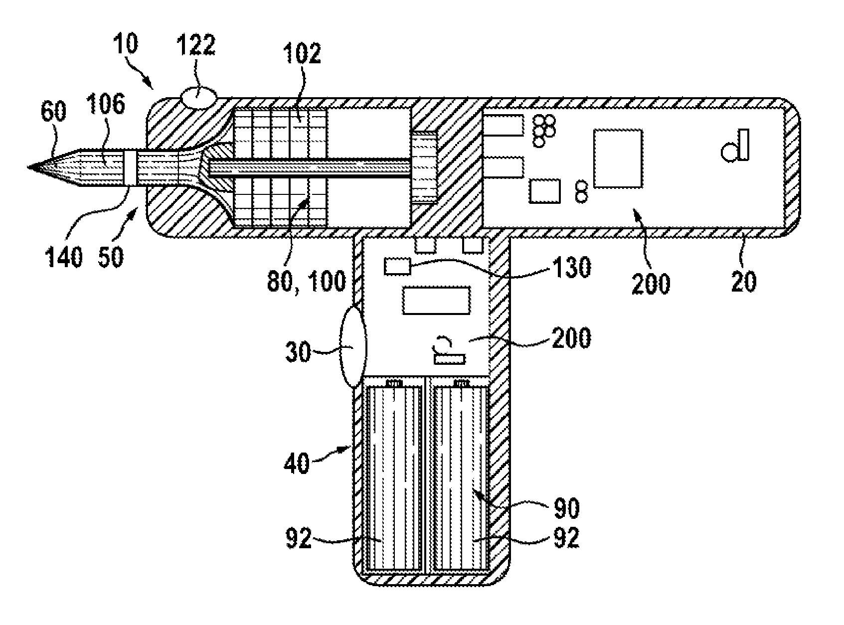
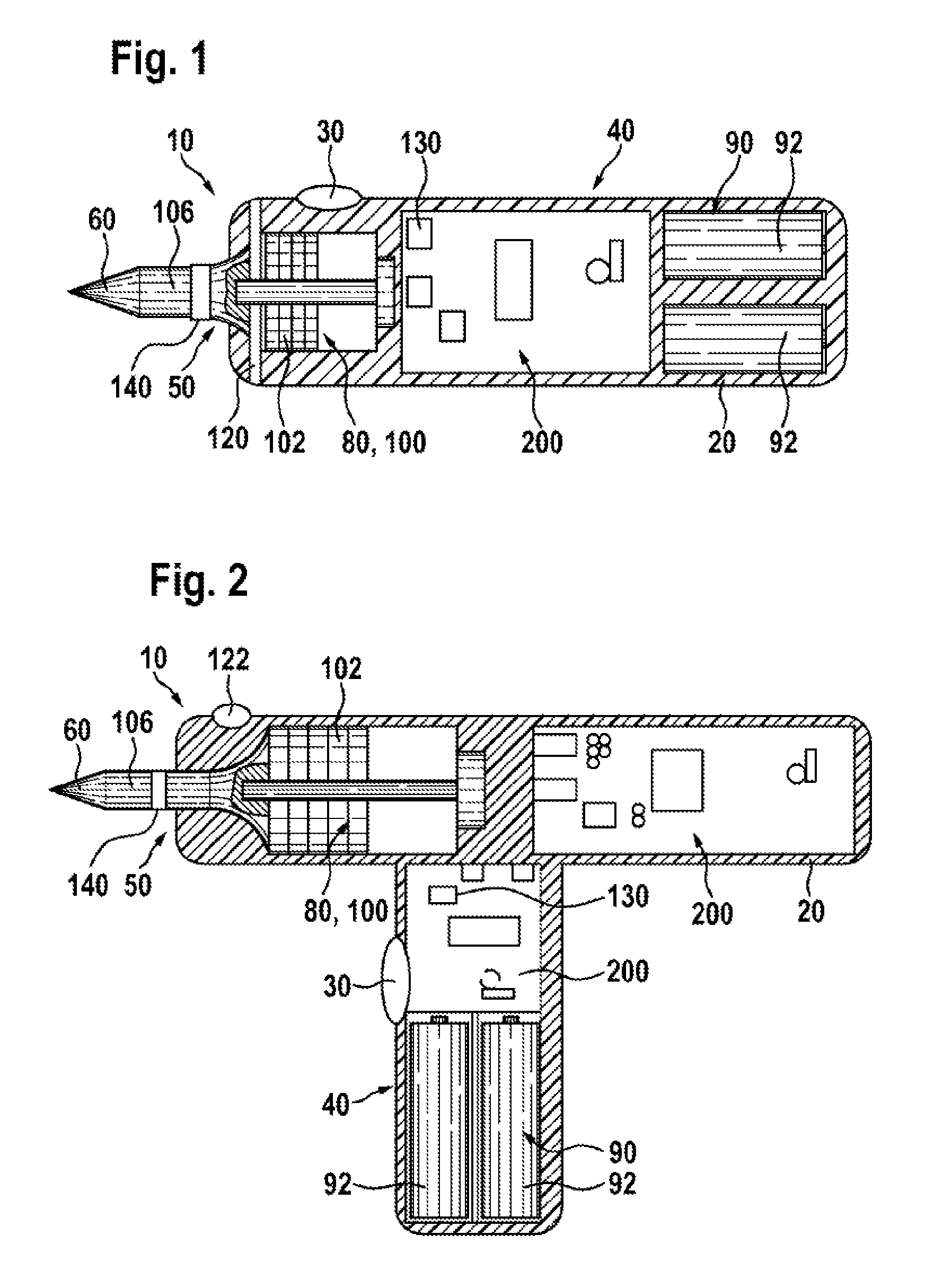
[0029]In order to explain the invention, FIGS. 1 and 2 show different examples of hand-held power tools 10. FIG. 1 shows a cutting appliance having an elongate housing form; FIG. 2 shows a drill having a T-shaped housing form.

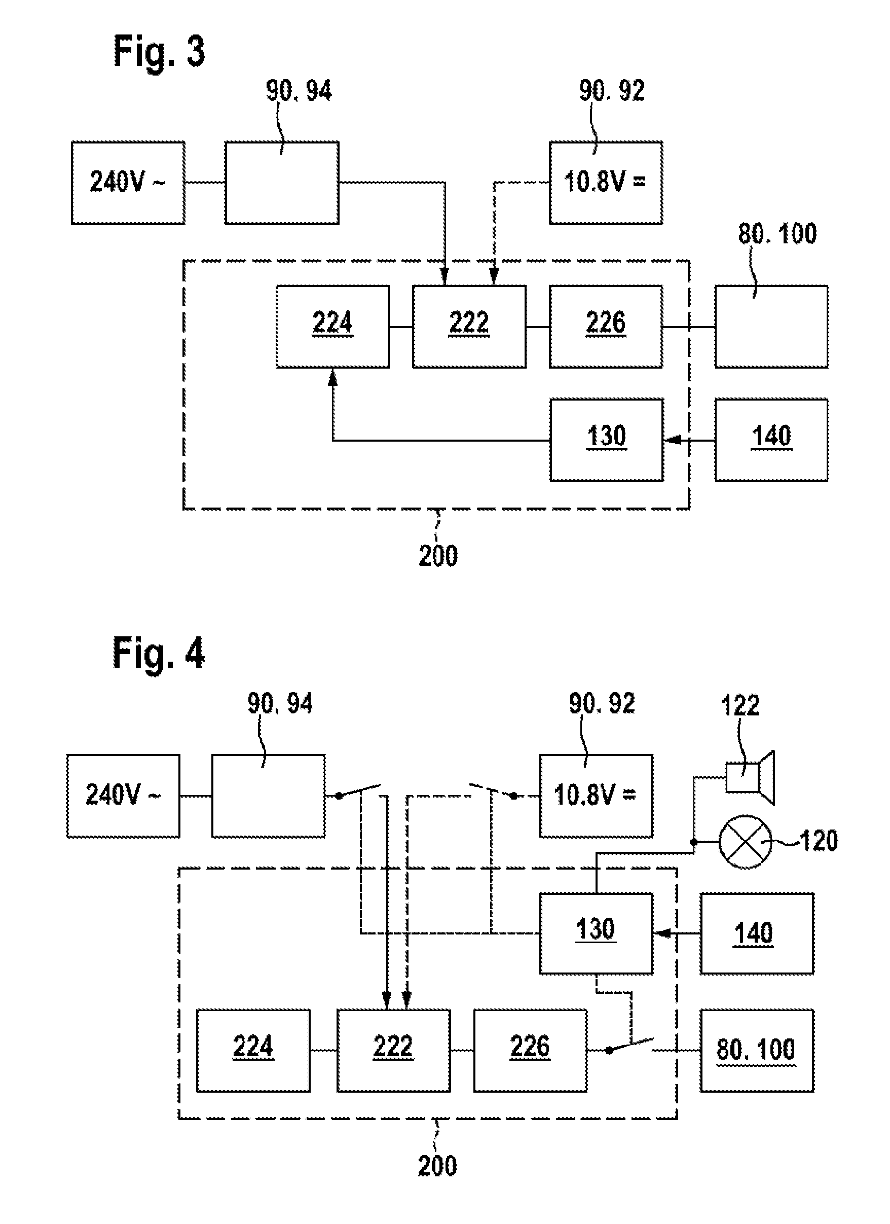
[0030]The hand-held power tool 10 comprises a housing 20 having a handle region 40. An operator holds the power tool 10 on the handle region 40 and can control the power tool 10. The power tool 10 also comprises a tool region 50 for a tool 60, for example a blade (FIG. 1) or a drill (FIG. 2) or another tool corresponding to another type of appliance, which can be driven in a linear and / or oscillating manner. A housing-mounted operator control part 30 can be used for activation of the tool 60 and / or the power tool 10 by a user.

[0031]A drive unit 80 is arranged in the housing 20, said drive unit comprising only one drive component, which is formed by an e...


PUM


Abstract

The disclosure relates to a hand-held power tool comprising a housing having a handle portion, a tool portion for a tool that can be driven to move linearly and / or oscillate, an operator part on the housing side for the activation of the tool and / or the power tool on the user side, a drive unit for producing a working movement of the tool, an electronic unit for supplying the drive unit at least with open-loop control and / or closed-loop control signals, and an operating voltage unit for making an electrical DC voltage available, the drive unit comprising at least one excitation actuator having a volume of an excitation-active material, which actuator is supplied with power by the operating voltage unit when operated and which is controlled in an open or closed loop control by the electronic unit.

Description

PRIOR ART[0001]The invention proceeds from a hand-held power tool comprising a housing having a handle region, a tool region for a tool which can be driven in a linear and / or oscillating manner, a housing-mounted operator control part for activation of the tool and / or power tool by a user, a drive unit for generating a working movement of the tool, an electronics unit for supplying at least open-loop and / or closed-loop control signals to the drive unit, an operating voltage unit for providing an electrical DC voltage, with the drive unit comprising at least one excitation actuator having a volume of excitation-active material, which excitation actuator is supplied with electrical power by the operating voltage unit during operation and is subjected to open-loop control or closed-loop control by the electronics unit.[0002]Hand-held power tools are distinguished by the fact that they are portable and are held and controlled by hand by an operator during operation. Said hand-held power...

Claims


Application Information

Patent Timeline
Patent Type & Authority Applications(United States)
IPC IPC(8): H02H1/00
CPCB23Q11/0078H02H1/0007F16P3/12B25F5/00
Inventor ROSER, JOCHEN
Owner ROBERT BOSCH GMBH
Learn More